36
11 Commissioning
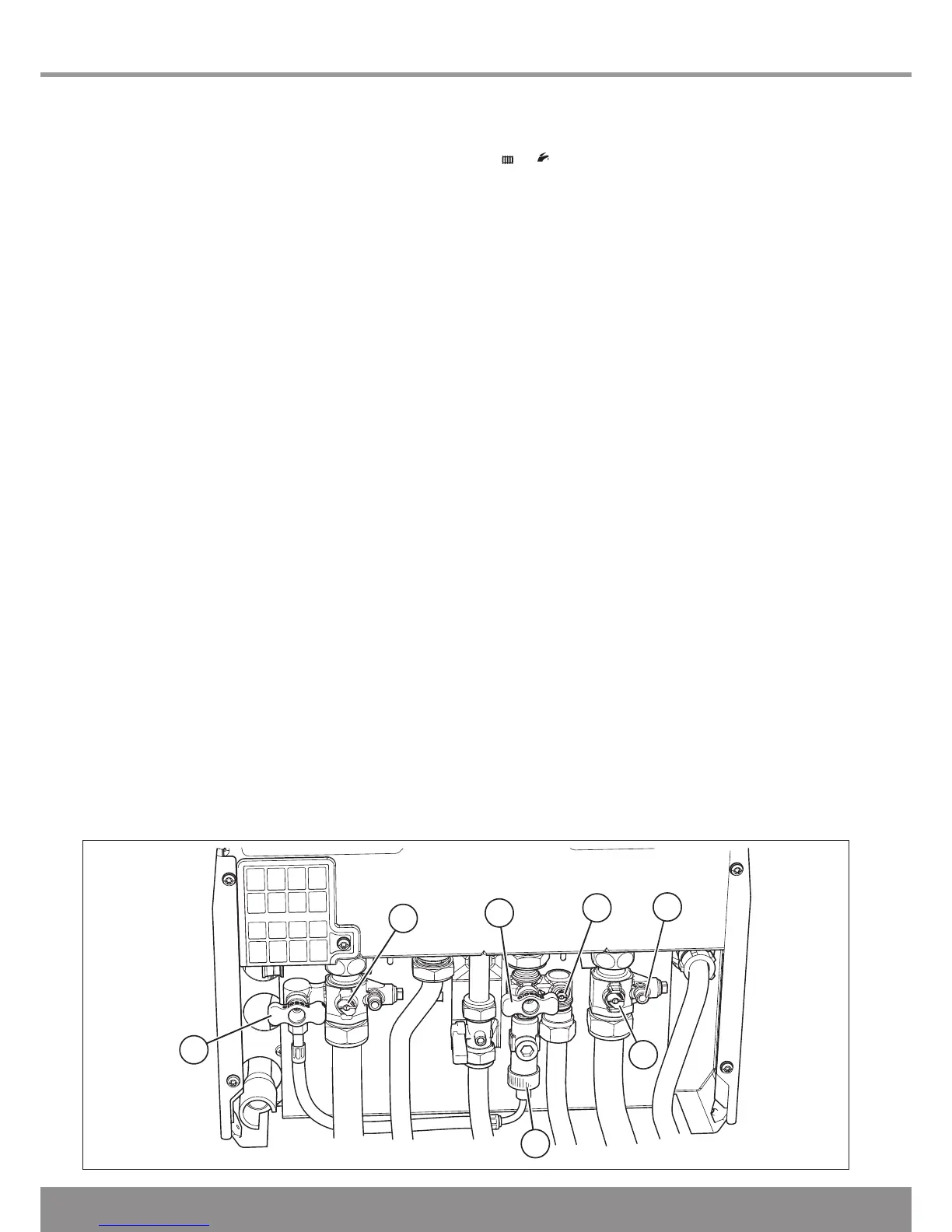
11.1 Pre-filling the Heating Circuit
Refer to diagram 11.1
1. Ensure that the flexible hose is connected to the double
check valve by tightening the knurled nut marked ‘E’.
2. Ensure that the water cocks are securely tightened onto the
jig blanking plugs.
3. Open the Central Heating Flow and Return cocks marked
‘A’ using a screwdriver or a 4mm allen key - slot in line with
the axis of the cock (shown closed in diagram).
4. Open the Domestic Cold Water cock marked ‘B’ using a
screwdriver or a 3mm allen key - slot in line with the axis of
the cock (shown closed in diagram).
NOTE: A manometer kit accessory, part no. 0020016995 is
available to monitor system pressure during filling, this should
be attached to the drain point connection marked ‘C’ and the
drain point opened to enable a reading of the system pressure
to be taken. If the manometer kit is not used caution should
be taken not to overpressurise the system.
5. Open the two filling taps marked ‘D’ by rotating them
through 90
o
to fill the heating system to a pressure of
1.0bar. Close the two filling taps marked ‘D’.
6. Vent all air from the system - repeat step 5 as neccessary
until the system is full and all the air has been removed.
7. Close the Domestic Cold Water cock marked ‘B’ using a
screwdriver or a 3mm allen key (shown closed in diagram).
8. Close the Central Heating Flow and Return cocks marked
‘A’ using a screwdriver or a 4mm allen key (shown closed
in diagram). If the manometer kit was used, close drain
point marked ‘C’ and remove the manometer.
9. To comply with the water regulations the flexible hose must
be disconnected from the double check valve - undo the
knurled nut marked ‘E’ and pull the flexible hose from the
double check valve.
11.2 Filling the System
With the boiler in place:
1. Ensure that the flexible hose is connected to the double
check valve by tightening the knurled nut marked ‘E’.
2. Open the Central Heating Flow and Return cocks marked
‘B’ using a screwdriver or a 4mm allen key - slot in line with
the axis of the cock (shown closed in diagram).
3. Open the Domestic Cold Water cock marked ‘B’ using a
screwdriver or a 3mm allen key - slot in line with the axis of
the cock (shown closed in diagram).
4. Switch on the appliance.
Set the Central Heating temperature and the Domestic Hot
Water temperature to OFF by pressing the MODE button
on the User Interface until it shows the appropriate symbol
and then pressing the - (minus) SELECTOR
button.
The display will now permanently show system pressure.
5. Open the two filling taps marked ‘D’ by rotating them
through 90
o
to fill the heating system to a pressure of
1.0bar. Close the two filling taps marked ‘D’.
6. Vent all air from the system - repeat step 5 as neccessary
until the system is full and all the air has been removed.
7. After filling is complete set the Central Heating temperature
and the Domestic Hot Water temperature to the desired
level using the MODE and + (plus) SELECTOR buttons as
described above.
8. To comply with the water regulations the flexible hose must
be disconnected from the double check valve - undo the
knurled nut marked ‘E’ and pull the flexible hose from the
double check valve.
11.3 Filling Domestic Water Circuit
Fully open any valves in the domestic water supply to the
boiler.
Open the domestic water isolation valve, slot in line with the
length of the valve (shown closed in diagram).
Open all hot water taps in turn and close them when water
flows. Check for water soundness of the complete domestic
water system.
The water flow rate is restricted by a restrictor factory fitted to
the boiler.
11.4 Re-pressurising System
1. Ensure that the flexible hose is connected to the double
check valve by tightening the knurled nut marked ‘E’.
2. Open the two filling taps marked ‘D’ by rotating them
through 90
o
to fill the heating system to a pressure of
1.0bar. Close the two filling taps marked ‘D’.
3. Vent all air from the system - repeat step 2 as neccessary
until the system is full and all the air has been removed.
4. To comply with the water regulations the flexible hose must
be disconnected from the double check valve - undo the
knurled nut marked ‘E’ and pull the flexible hose from the
double check valve.
Diagram 11.1
13133
 Loading...