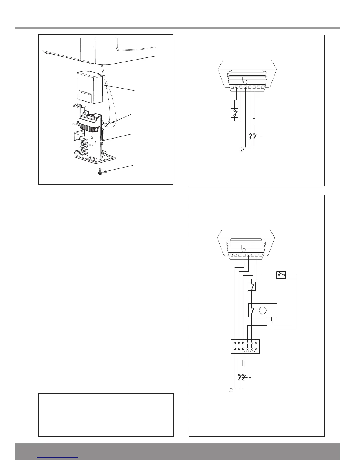
Diagram 10.3
12612
Diagram 10.2
12611
WARNING: This appliance must be earthed.
This appliance must be wired in accordance with these
instructions. Any fault arising from incorrect wiring cannot be
put right under the terms of the Glow-worm guarantee.
All system components must be of an approved type.
Electrical components have been tested to meet the
equivalent requirements of the BEAB.
Do not interrupt the mains supply with a time switch or
programmer.
Connection of the whole electrical system and any heating
system controls to the electrical supply must be through a
common isolator.
Isolation should preferably be by a double pole switched
fused spur box having a minimum contact separation of
3mm on each pole. The fused spur box should be readily
accessible and preferably adjacent to the boiler. It should be
identified as to its use.
10.1 Mains Supply Cable
The appliance mains supply cable should be permanently
connected to a cable anchorage. The cable anchorage shall
relieve conductors from strain, including twisting, at the
terminals and protect the insulation of the conductors from
abrasion.
10.2 Electrical Connections - Testing
Carry out preliminary electrical system checks as below:
1. Test insulation resistance to earth of mains cables.
2. Test the earth continuity and short circuit of cables.
3. Test the polarity of the mains.
IMPORTANT NOTE
ALL electrical connections to the boiler
must be permanently fixed to a wall or a
sturdy support feature in a tidy manner.
 Loading...