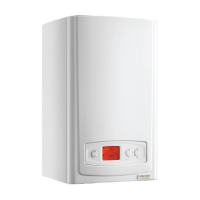
14.27 Control Box
For access, refer to section 14.1.
Hinge down the control box and unclip the rear cover to gain
access.
Remove relevant electrical connections from main PCB and
grommets from the control box.
IMPORTANT:
Support the control box whilst undoing the
hinges.
Remove the hinge securing screws accessed from beneath
the boiler and remove the control box, see diagram 14.25.
14.28 Fuse - Main PCB - Control Box
For access, refer to section 14.26.
The fuse is located at the top left hand corner of the main
PCB, see diagram 14.23.
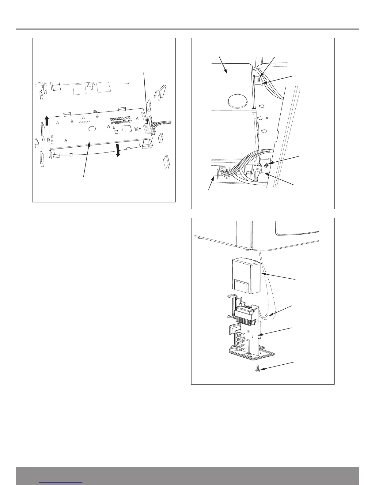
14.29 Installer Interface
Remove the Installer Interface securing screw accessed from
beneath the boiler.
Carefully pull down the Installer Interface to remove, see
diagram 14.26.
Diagram 14.25
13004
 Loading...