48
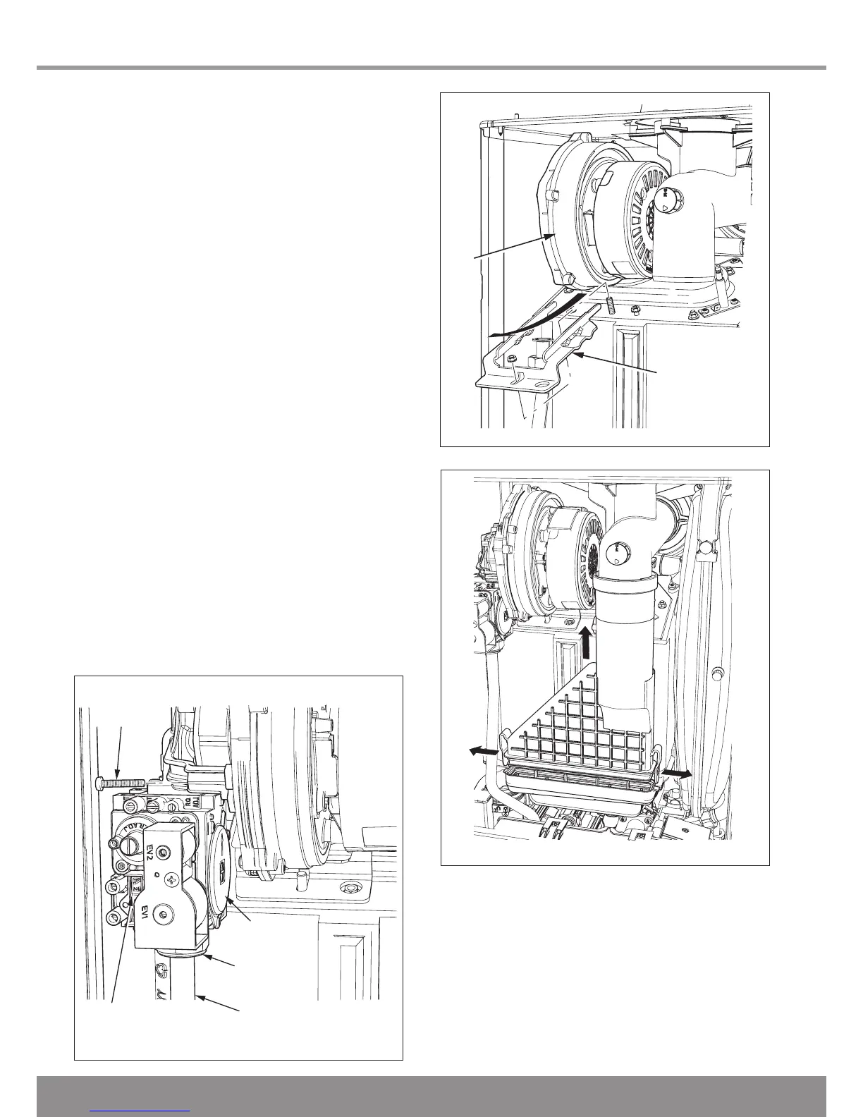
14.7 Gas Valve
Remove rear silencer.
Remove the three securing screws, holding the gas valve to
the fan, see diagram 14.4.
Remove the gas valve.
After re-fitting check the combustion CO
2
and adjust if neces-
sary, see section 12.6.
After assembly test for gas soundness and purge in accord-
ance with the current issue of BS6891or in IE, the current
edition of I.S.813 “Domestic Gas Installations”.
14.8 Flue Hood
For access, refer to section 14.1.
Pull the flue hood securing clips away from the flue hood
sump and push flue hood up slightly towards flue hood top,
see diagram 14.6.
To remove swivel flue hood 90
0
and pull down and out to-
wards front of boiler, see diagram 14.7.
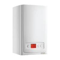
14.9 Fan
For access, refer to section 14.1.
Remove the gas valve as described in the relevant parts of
section 14.7.
Remove the securing nut holding the fan retaining bracket,
lift front of bracket away from stud and pull forward to release
the fan, see diagram 14.5, check and replace any seals or
gaskets if necessary.
14 Replacement of Parts
 Loading...