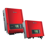
120Ω Termination
Resistor Dip Switch
Earthing of shield
RS485 Terminal
EzLogger Pro
Ethernet
Router
PC
RS485-OUT
RS485-IN
RS485-OUT
RS485-IN
RS485-OUT
RS485-IN
120Ω
Inverter Inverter Inverter
Internet
RS485-OUT
If several DT inverters linked together with Ezlogger Pro, the inverter number in daisy chain could
be 20 at most.
4.4.2 Wi-Fi Communication
The Wi-Fi Communication function is only applied for WIFi Module, for detailed configuration
instruction refer to "Wi-Fi Configuration Instruction" in the accessory box.
After configuration, please browse the monitoring portal website to create PV station
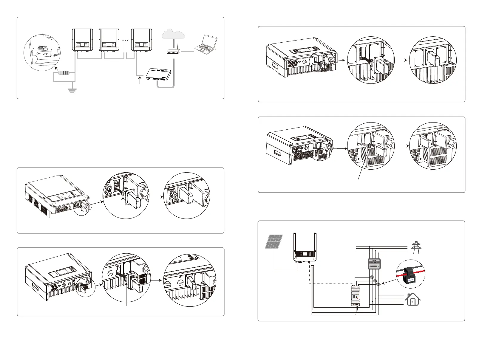
The WiFi module installation of DT series are shown as below.
Connect the cable terminal with the external WiFi module
The WiFi module installation of SDT 4-10KW are shown as below.
Connect the cable terminal with the external WiFi module
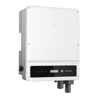
4.4.4 Export Power Limit Connection Diagram
The methods of connecting the Power Limiting device is shown below.
CT A connect to L1
CT B connect to L2
CT C connect to L3
Power Meter
PV
Inverter
“To Smart Meter”
Loads
Grid
PE
N
L3
L2
L1
Grid
House→Grid
Smart Meter
N
L
Reset
SMART METER
USB
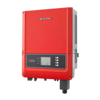
Installation of SDT 10KL / 12-15KW external Wi-Fi module
Connect the cable terminal with the external WiFi module
Installation of SDT 17-20KW external Wi-Fi module
Connect the cable terminal with the external WiFi module
1615