46
06 Electrical Connection
User Manual V1.6-2024-03-20
NOTICE
• The smart meter and CT have been preset parameters before delivered with the inverter.
Do not modify the relevant parameters.
• The BMS communication cable and meter communication cable are delivered with the
inverter, with default length of 3m and 10m respectively.
• Each inverter needs to be connected to one smart meter independently. Do not connect
one smart meter to multiple inverters. Contact the manufacturer or supplier to purchase
additional smart meter(s) if you need.
• Ensure that CT connects with the corresponding phase line: CT1 is connected to L1; CT2 is
connected to L2; and CT3 is connected to L3. And ensure that the CT is connected in the
right direction. Please refer to the smart meter user manual for detailed operations.
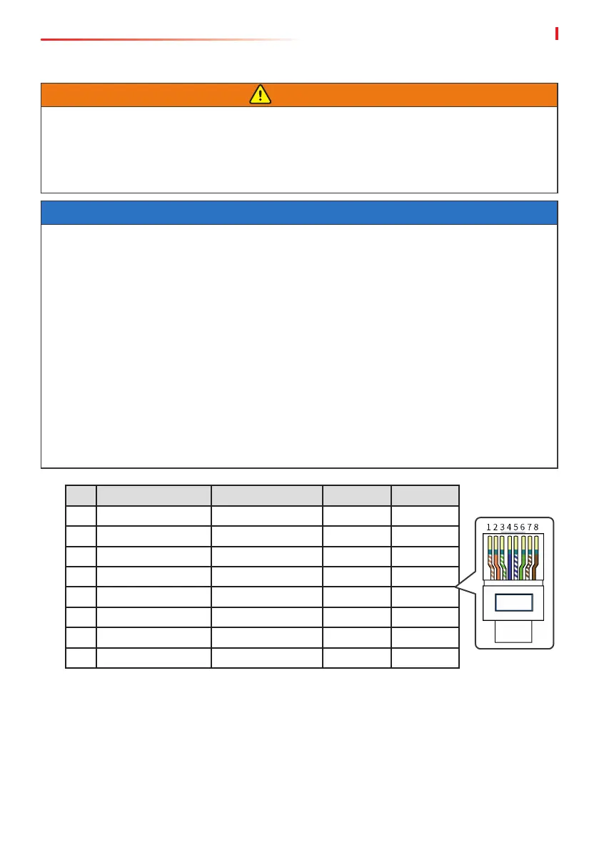
• Use the included BMS communication cable to realize communication between the inverter
and the battery. Otherwise, the communication may fail. If more communication cables
are needed, please prepare network cables and RJ connectors by yourself to make the
cable. Only crimp PIN4 and PIN5 of the connector when making the cable, otherwise the
communication may fail.
PIN Color Smart Meter BMS1 BMS2
1 Orange and White NC NC NC
2 Orange NC NC NC
3 Green and White NC NC NC
4 Blue NC CANH1 CANH2
5 Blue and White NC CANL1 CANL2
6 Green NC NC NC
7 Brown and White 485_B1 NC NC
8 Brown 485_A1 NC NC
6.7.2 Connecting the BMS or Meter Communication Cable
WARNING
• For GW15K-ET and GW20K-ET, please connect the cable to BMS1 port to realize BMS
communication. Otherwise, BMS communication may fail.
• For GW25K-ET, GW29.9K-ET, and GW30K-ET, please connect the cable to BMS1 port to
realize BMS communication when single battery system is connected. Otherwise, BMS
communication may fail. For more details, refer to 6.5 Connecting the Battery Cable.

 Loading...