ProBellSystemInformation
ProBell ProBell
ProBell
System System
System
Information Information
Information
Thismanualprovidesinstructionsonhowtocomplete
theassemblyofacart-mountedProBellRotary
ApplicatorSystem,whichincludesthefollowing
components.
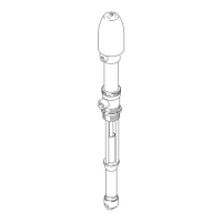
•TheRotary Rotary
Rotary
Applicator Applicator
Applicator
comesinvariousmodels.
SeetheModelslistforapplicatorsthatareavailable
withasystem.Manuals334452or334626arethe
mainsourceofsysteminformation.Theyinclude
installationandoperationinstructionsaswellas
maintenanceandrepairinformation.
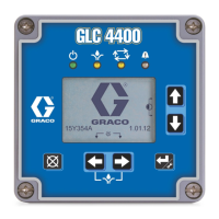
•TheSystem System
System
Logic Logic
Logic
Controller Controller
Controller
controlsandmonitors
therotaryapplicatorsystemfunctionsthrough
theuserinterfaceorthroughcommunicationwith
aPLC.ASystemLogicControllerisrequiredif
yoursystemincludesaSpeedControlleroranAir
Controller.MounttheSystemLogicControllerin
thenon-hazardousarea.Manual3A3955contains
allinformationneededtounderstandthesetupand
operationofthesystemviatheuserinterface.It
alsocontainsdetailedtroubleshootingandevent
codeinformation.
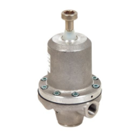
•TheSpeed Speed
Speed
Controller Controller
Controller
directstheturbineairand
brakeairtotheapplicator.Thecontrollerusesa
beropticsignalfromtheProBellapplicatorto
providepreciseclosed-loopcontrolofthebellcup
rotationspeed.TheSpeedControllermustbe
mountedinthenon-hazardousarea,ascloseto
theapplicatoraspossibletominimizepressure
lossintheairlines.Manual3A3953contains
specicinstallation,troubleshooting,repair,and
partsforthiscomponent.
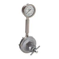
•TheAir Air
Air
Controller Controller
Controller
electronicallycontrolstheinner
andoutershapingair.Italsoprovidesairactivation
signalsforthepaint,dump,andsolvent(cupwash)
valvesintheapplicator.MounttheAirControllerin
thenon-hazardousarea,asclosetotheapplicator
aspossibletominimizepressurelossinthe
airlines.SeeManual3A3954forinstallation
instructionsandfeaturesofeachaircontroller,
specicinstallation,troubleshooting,repair,and
partsforthiscomponent.
•TheElectrostatic Electrostatic
Electrostatic
Controller Controller
Controller
sendspowertothe
applicatorpowersupply,whichincreasesthe
voltagetothelevelsetatthecontroller.Itmust
bemountedinthenon-hazardousarea.See
ProBellElectrostaticControllermanual3A3657
forallinformationneededtounderstandthisuser
interface.
•TheTwenty Twenty
Twenty
Meter Meter
Meter
(65 (65
(65
ft) ft)
ft)
Hose Hose
Hose
Bundle Bundle
Bundle
Kit Kit
Kit
includes
9airlines,aberopticcable,powersupplycable,
groundingcable,and3uidlines(purchaseuid
linesseparatelyforwaterbornesystems).
•TheCGM CGM
CGM
(CommunicationGatewayModule)
providesacontrollinkbetweentheProBellsystem
andaselectedeldbus.Thislinkageprovides
themeansforremotemonitoringandcontrolby
externalautomationsystems.TheProBellsystem
supportsModbusTCP,EtherNet/IP,DeviceNet,
andPROFINET.Onegatewaycansupporttwo
ProBells.SystemrequiresaProBellsystemCGM
installationkitandgateway.Seethefollowing
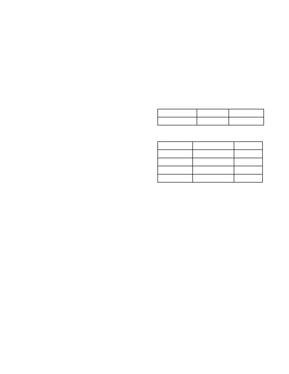
tables.
Table Table
Table
1 1
1
ProBell ProBell
ProBell
System System
System
CGM CGM
CGM
Installation Installation
Installation
Kit Kit
Kit
PartNumberFieldBusManual
24Z574All3A4384
Table Table
Table
2 2
2
Communication Communication
Communication
Gateway Gateway
Gateway
Module Module
Module
PartNumberFieldBusManual
CGMDN0
DeviceNet312864
DGMEP0
EtherNet/IP312864
DGMPN0PROFINET
312864
24W462
ModbusTCP
334183
Electrical Electrical
Electrical
Inputs Inputs
Inputs
and and
and
Outputs Outputs
Outputs
ThefollowingdiscreteI/Oconnectionscanbeused
todrivethesystemremotely.
Speed Speed
Speed
Controller Controller
Controller
•Systemstatusoutput
•OptionalInterlockinput
Electronic Electronic
Electronic
Air Air
Air
Controller Controller
Controller
•PaintTriggerInput
•OptionalInterlockInput
Electrostatic Electrostatic
Electrostatic
Controller Controller
Controller
•Safe-to-MoveOutput
•ErrorOutput
•ActualSprayingCurrentOutput
•ActualSprayingVoltageOutput
•ElectrostaticsDischargedOutput
•SAFEPOSITIONInterlockInput
•24VDCInterlockInput
•SystemInterlock
•ElectrostaticEnableInput
3A4232D9
 Loading...