Repair
48 311075R
Fluid Heaters (if supplied) Pressure Transducers
2. Remove access cover (39) at back of con-
trol module to expose control board (406).
3. Disconnect transducer cables from J3 and
J8 at board; see F
IG. 12, page 47. Reverse
A and B connections and check if status
code follows the bad transducer, page 32.
4. Reconnect good transducer to proper con-
nector. Disconnect failed transducer from
board, and unscrew from base of fluid
heater (heated units) or transducer mani-
fold (nonheated units).
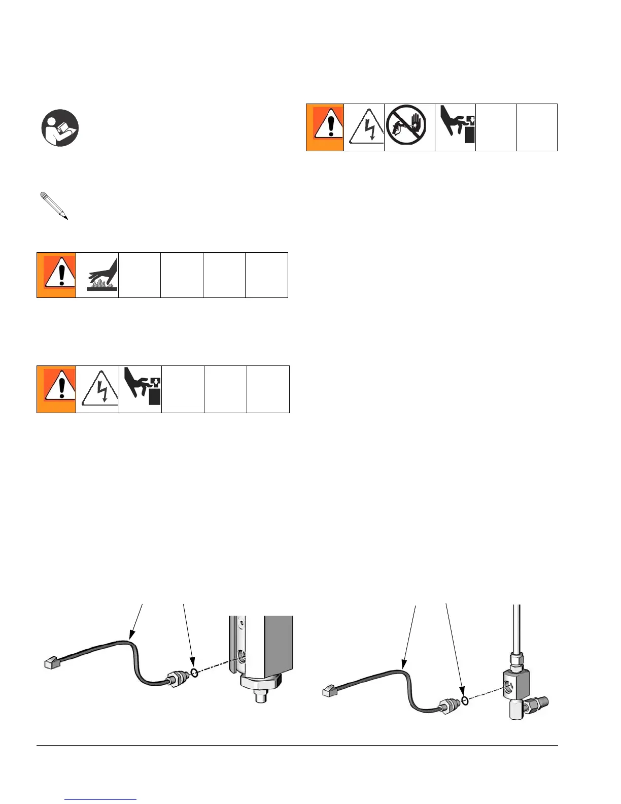
5. Install o-ring (60) on new transducer (58),
F
IG. 13.
6. Install transducer in heater or manifold.
Mark board end of cable with tape
(red=transducer A, blue=transducer B).
7. Route cable through channel to control
module.
8. Connect transducer cable at board; see
FIG. 12, page 47.
Fluid heater repair and parts
information is included in manual
311210, which is supplied with heated
units.
To replace a pressure transducer, see
at right.
1. See Before Beginning Repair, page 39.
Relieve pressure, page 27.
2. Control section of heater can be repaired in
place. Remove heater to clean fluid section.
See manual 311210 for heater repair and
parts.
1. See Before Beginning Repair, page 39.
Relieve pressure, page 27.
FIG. 13. Transducers
6058
Heated Units
Nonheated Units
6058
TI7026a
TI7027a

 Loading...