9 / 24
16570.123_V1sh
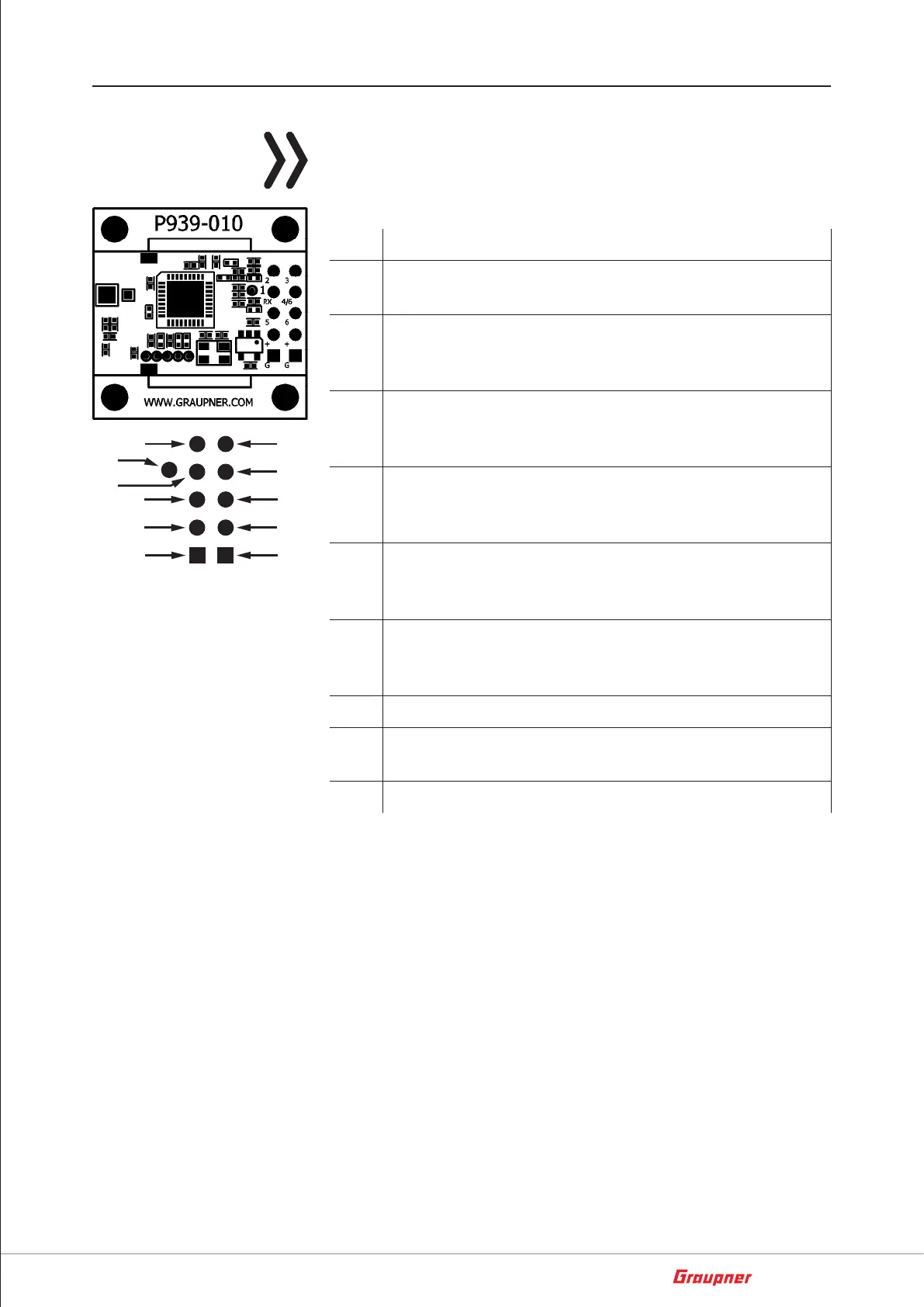
Connection points of the circuit board
Note
For the sake of clarity, the lower figure shows the spatial placement
of the connection points and their designations enlarged according
to the scheme used on the board.
Description
1 Channel 9 with switching function to set the FPV transmit
channel of pin CS3 or to switch LEDs by transistor
2 Channel 10
Switching function to set the FPV transmit channel of pin
CS2 or to switch LEDs by transistor
3 Channel 11
Switching function to set the FPV transmit channel of pin
CS1 or to switch LEDs by transistor
4/6 Channel 6 or SUMD or SBUS or SP2048
Switch through telemetry menu
(Factory setting SUMD)
5 Channel 5 or telemetry
Switch through telemetry menu
(Factory setting TELEMETRY)
6 Channel 6 or SUMD or SBUS or SP2048
Switch through telemetry menu
(Factory setting SUMD)
RX Telemetry connection for Full-Duplex-Use, e.g. for inav
+ Positive pole connection
Input voltage range 4... 10V
G Ground connection (GND = negative pole of the battery)
After binding, the channels 1 ... 3 are output at the connections 1 ...
3 as a servo function. After a factory reset, the channels 9 ... 11 are
output as switching channels at the terminals 1 ... 3 so that the FPV
channels of an FPV video transmitter 16570.123 can be conveniently
set via the transmitter.
On the following pages you will find some connection examples to
the Omnibus flight controls, which can stabilize both Copter with
Betaflight or inav software, as well as surface models with inav. Rec-
ommended for surface models the flight control 48374.PROV3.
Recommended for copters with GPS the flight control 48374.PROV3
or 48374.MPU6000 or 48377
1
5
+
+
6
 Loading...