www.modellmarkt24.ch; www.modellmarkt24.de
3.1. CONNECTIONS
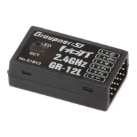
3. RECEIVER
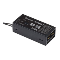
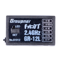
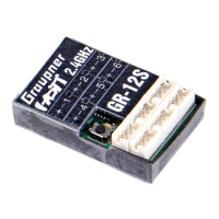
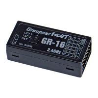
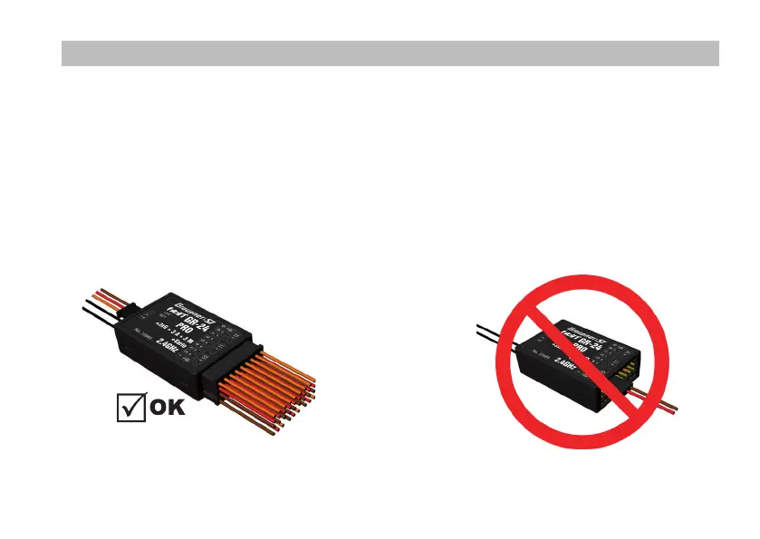
Connect the servos to the row of sockets on one end of the receiver. The connectors are polarised: note the small chamfers
on one side. Never use force - the connectors should engage easily. The polarity is also printed on the receiver;
the negative wire (-) is brown, the positive (+) red and the signal orange.
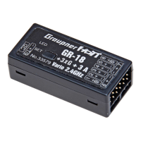
The servo sockets of Graupner/SJ HoTT 2.4 receivers are numbered sequentially. The socket for channel 6 can also be
programmed to deliver a (digital) sum signal (see section 3.2: Receiver set-up).
I²C (Inter-Integrated Circuit) - socket currently not active; for servicing purposes only!
Power supply
47
www.modellmarkt24.ch; www.modellmarkt24.de
 Loading...