8 - 29
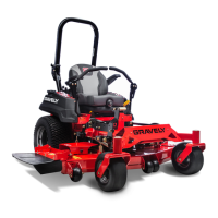
Standard on Promaster 160 and 200
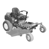
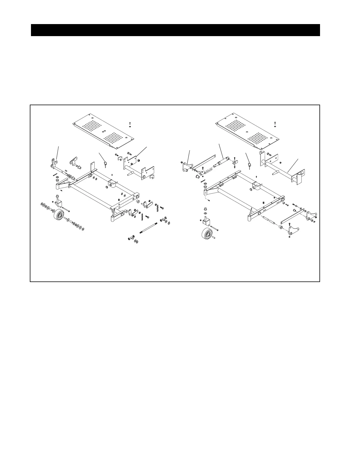
The mower lift system consists of the mower frame
with caster wheels, the hydraulic pump and reservoir,
and the hydraulic lift cylinder with linkage.
8.1 MOWER FRAME
To remove mower frame, Figure 17:
1. Remove mower deck.
2. Disconnect the hydraulic cylinder from the lift arm
weldment.
3. Pull the pin at the rear center pivot.
4. The frame can be moved forward off the center
pivot and pulled out.
5. Install in reverse order
8.2 CHECK CASTER WHEELS FOR WEAR
To replace caster bushings:
1. Pull cotter pin at top of shaft.
2. Drop caster out from the bottom.
3. Clean shaft and grease.
4. Replace washers and bushings and reassemble.
5. Apply grease.
8.3 TO REPLACE WHEEL AXLE
1. Remove nut from axle bolt and pull axle bolt out.
Inspect roller bearing. Clean roller and replace if
needed.
2. Grease axle bolt, roller, and wheel hub.
3. Reassemble axle. Tighten locking nut to remove
play but allow wheel to turn.
8.4 LINKAGE
Inspect lift linkage for wear. Replace bushings by
removing the lift arm weldment and sliding the old
bushing out.
8.5 HYDRAULIC SYSTEM
SECTION 8 - MOWER LIFT SYSTEM
PF1980
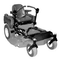
Figure 17
1. Mower Lift Shaft Weldment
2. Klik Pin
3. Mower Frame Mounting
4. Hydraulic Cylinder
5. Lift Arm Weldment
1
2
2
3
3
4
1
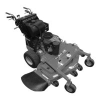
50" Mower
60" Mower
 Loading...