EasyManuals Logo

Gravely Promaster 200 User Manual

Gravely Promaster 200
80 pages
To Next Page IconTo Next Page
To Previous Page IconTo Previous Page
Page #32 background imageLoading...
Page #32 background image
9 - 32
9.1 STEERING AND DIRECTION
CONTROLS
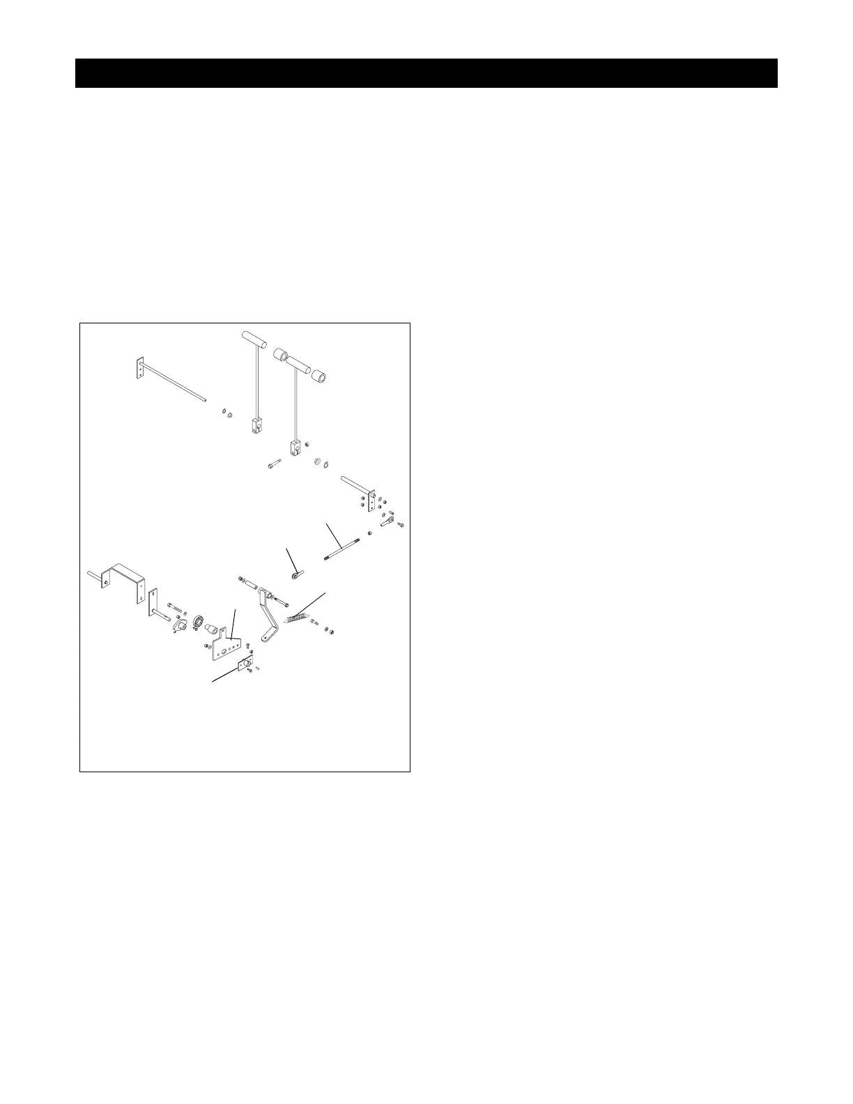
1. Remove the tension spring, Figure 19.
2. Unbolt the steering rod end from the speed control
arm.
3. Remove the neutral adjustment weldment and
inspect woodruff key
4. Inspect bearing and pivot points for wear and
replace as needed.
5. Assemble in reverse order.
SECTION 9 - STEERING AND DIRECTION CONTOLS
PF2000
1
2
3
4
5
Figure 19
1. Steering Adjusting Rod
2. Rod End
3. Tension Spring
4. Speed Control Arm
5. Neutral Adjustment
Weldment

Table of Contents

Questions and Answers:

Question and Answer IconNeed help?

Do you have a question about the Gravely Promaster 200 and is the answer not in the manual?

Gravely Promaster 200 Specifications

General IconGeneral
BrandGravely
ModelPromaster 200
CategoryLawn Mower
LanguageEnglish

Related product manuals