13 - 51
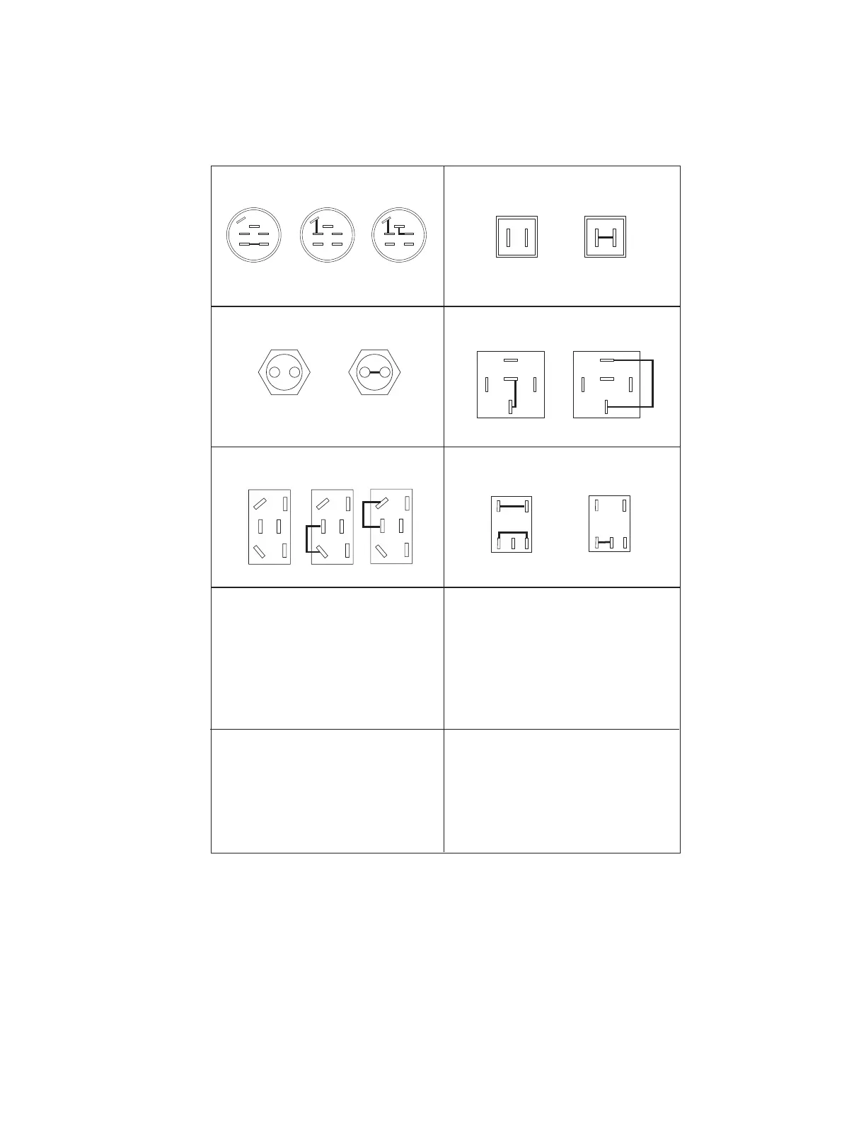
13.12 CONTINUITY DIAGRAMS
Models 991005, 006, 007, 008
OFF
M
G
S2
B
S1
A
RUN
M
G
S2
B
S1
A
START
M
G
S2
B
S1
A
87
87A
86 85
30
NOT ENERGIZED
87
87A
86 85
30
ENERGIZED
1
OPERATOR
OFF SEAT
2
1
OPERATOR
ON SEAT
2
button out
button in
Key Switch
(03602300)
Relay
(03042800)
Seat Switch
(03654200)
Switch - Neutral Start N.O.
(020916)
Lift Pump Switch
(03437900)
PTO Switch
(00522100)
3
9
ENGAGED
(up position)
DISENGAGED
(down position)
The diagrams below show the various states of connection for electrical components.
The solid lines on switches show continuity.
NOTE: All switches are viewed from the rear.
4
1
7
3
9
4
1
7
1
2
DISENGAGED
1
2
ENGAGED
D
A
E
C
F
B
D
A
E
C
F
B
D
A
E
C
F
B
OFF UP DOWN
 Loading...