CONTENTS
PRODUCT ........................................................................................................................................................................ 2
1 MODELS LIST .......................................................................................................................................................... 2
1.1 Outdoor Unit ..................................................................................................................................................... 2
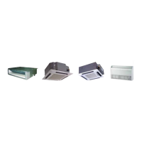
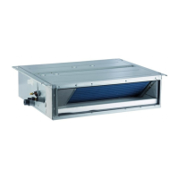
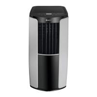
1.2 Indoor Unit ........................................................................................................................................................ 3
2 NOMENCLATURE ................................................................................................................................................... 4
2.1 Outdoor Unit ..................................................................................................................................................... 4
2.2 Intdoor Unit ....................................................................................................................................................... 4
3 PRODUCT DATA ...................................................................................................................................................... 5
3.1 Product Data of Indoor Unit ......................................................................................................................... 5
3.2 Operation Range ........................................................................................................................................... 11
3.3 Electrical Data ................................................................................................................................................ 11
4 PIPING DIAGRAM ................................................................................................................................................. 13
CONTROL ...................................................................................................................................................................... 15
1 OPERATION FLOWCHART ................................................................................................................................. 15
1.1 Cooling/Dry Operation ................................................................................................................................. 15
1.2 Heating Operation ......................................................................................................................................... 16
2 WIRELESS REMOTE CONTROLLER ................................................................................................................ 17
2.1 Operation and Display View ....................................................................................................................... 17
3 WIRED CONTROLLER ......................................................................................................................................... 19
3.1 Display View ................................................................................................................................................... 19
3.2 Operation View .............................................................................................................................................. 21
4 OPERATION INSTRUCTION OF SPECIAL FUNCTIONS ............................................................................... 24
5 INSTALLATION OF WIRED CONTROLLER ..................................................................................................... 24
5.1 Standard Accessories .................................................................................................................................. 24
5.2 Installation Position and Requirement .................................................................................................... 24
5.3 Installation of Wired Controller ................................................................................................................. 25
5.4 Removal of Wired Controller ...................................................................................................................... 26
6 TROUBLESHOOTING .......................................................................................................................................... 26
6.1 Display of Error Code ........................................................................................................................................... 26
7 CENTRALIZED CONTROLLER .......................................................................................................................... 27
7.1 Smart Zone Controller ................................................................................................................................. 27
7.2 Additional Special Functions ..................................................................................................................... 30
INSTALLATION.............................................................................................................................................................. 36
1 INDOOR UNIT INSTALLATION ........................................................................................................................... 36
1.1 Installation of Duct Type ............................................................................................................................. 36
1.2 Installation of Cassette Type ...................................................................................................................... 46
2 OUTDOOR UNIT INSTALLATION ....................................................................................................................... 55
2.1 Before Installation ......................................................................................................................................... 55
2.2 Installation Site .............................................................................................................................................. 56
2.3 Caution for Installation ................................................................................................................................ 56
2.4 Dimension Data ............................................................................................................................................. 57
3 REFRIGERATION PIPING WORK ...................................................................................................................... 58
3.1 Refrigeration Piping Work Procedures and Caution in Connecting ................................................ 58
3.2 Specification of Connection Pipe ............................................................................................................. 62
4 ELECTRIC WIRING WORK .................................................................................................................................. 63
4.1 Wiring Precautions ....................................................................................................................................... 63
4.2 Electrical Wiring ............................................................................................................................................ 63
MAINTENANCE ............................................................................................................................................................. 70
1 TROUBLE TABLE .................................................................................................................................................. 70
2 FLOW CHART OF TROUBLESHOOTING ......................................................................................................... 72
2.1 Troubleshooting Flow Chart of Main Control Malfunction ................................................................. 72
2.2 Interface ........................................................................................................................................................... 78
3 WIRING DIADRAM ................................................................................................................................................ 80
 Loading...