U-Match Series Service Manual
80
Compressor electrical heater
Compressor electric heating belt
Electronic expansion valve line
1 to 4-pin: Drive impulse output;5-pin:
+12V;
Interface of electronic expansion valve:
1 to 4-pin: Drive impulse output;
5-pin: +12V;
Low pressure switch for system
protection (obligate)
Interface of low pressure protection
High pressure switch for
systemprotection(obligate)
Interface of high pressure protection
1&2 pin: Tube sensor
3&4 pin: Ambient temperature
5&6 pin: Air discharge
1&2 pin: Case temperature sensor
3&4 pin: Ambient temperature sensor
5&6 pin: Discharge temperature sensor
High pressure switch for fan speed
adjustment
Pressure protection switch for fan speed
adjustment
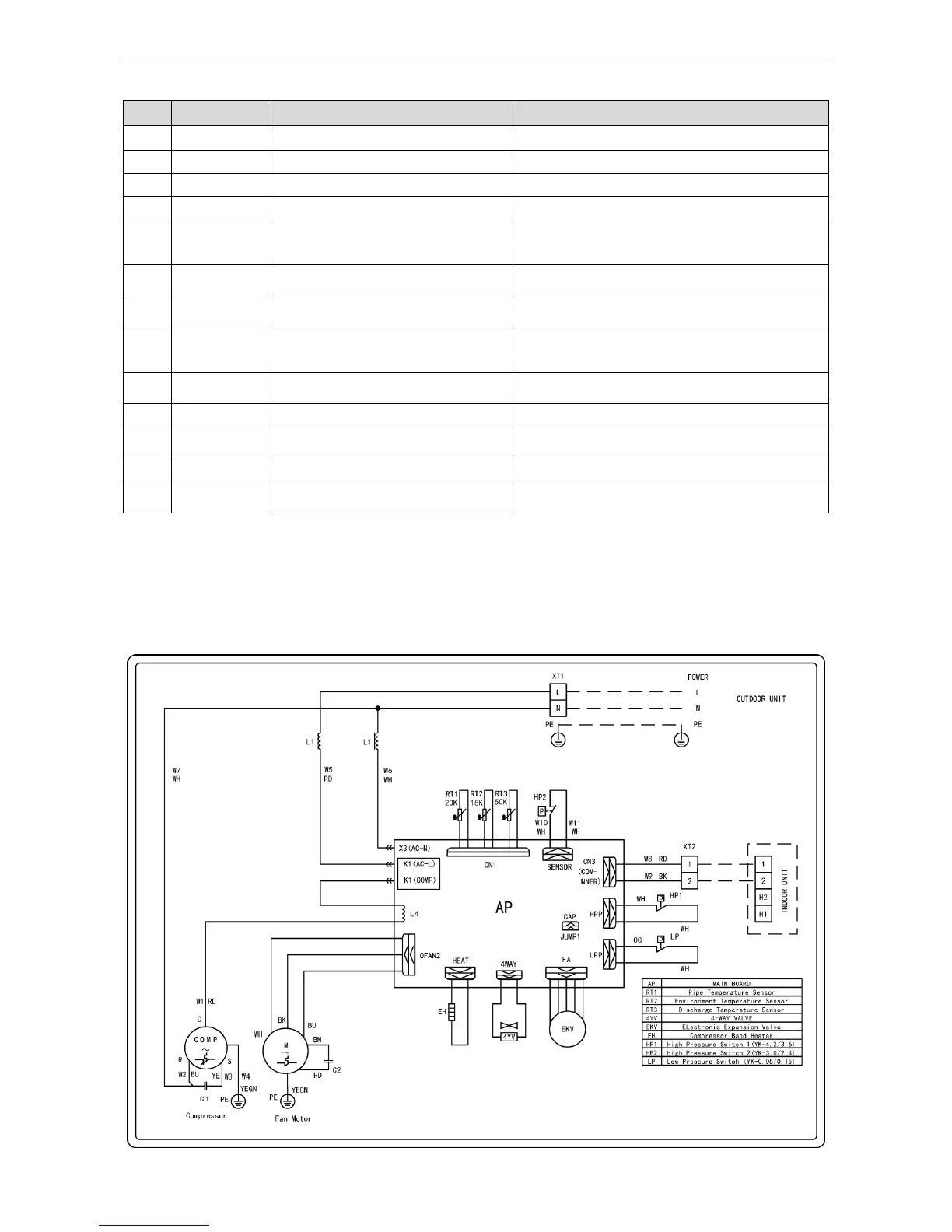
3 WIRING DIADRAM
3.1 Outdoor unit
The actual wiring should always refer to the wiring diagram of the unit.
Model: GUHN18NK3HO
 Loading...