GREE DC Inverter Multi VRF System II Service Manual
98
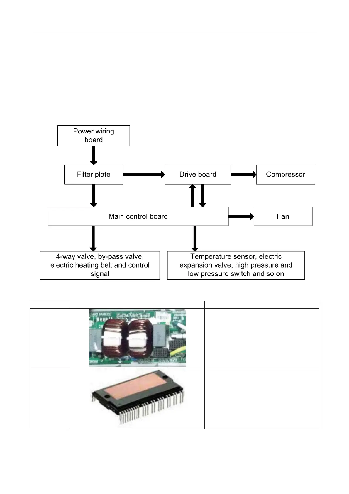
4 Power Distribution of Unit
4.1 Power distribution of unit
The control logical relationship among parts inside the electric box of unit is showed by the mongline
diagram (CAD source file).
The main loop is showed by bold line (line width: 1mm); the control loop is showed by slim line (line
width: 0.2mm).
˄Bold line is the power line and the slim line is the control line˅
4.2 Main electric parts
It main effect is to eliminate the interference of
power for protecting unit’s anti-inter
ference
capability and prevent the interference to other
electric appliances.
There are three complemental IGBT tube
inside the IPM module. They are controlled by
PWM wave and then bring the pressure of DC
bus bar
to different stator windings of
compressor at different stage, and then
generate current on the stator. Meanwhile,
magnetic field will be generated on the stator
winding, and push the operation of rotor and
then drive compressor to operate.
 Loading...
