GREE DC Inverter Multi VRF System II Service Manual
70
1.2 Debugging of unit
Debugging procedure for test run, display instruction for indicator on main board of outdoor unit and
operation method are as below:
GMV-80WL/A-T GMV-100WL/A-T GMV-121WL/A-T GMV-80WL/C-T GMV-100WL/C-T
GMV-121WL/C-T GMV-120WL/C-T GMV-140WL/C-T GMV-160WL/C-T GMV-120WL/C-X
GMV-140WL/C-X GMV-160WL/C-X
GMV-H224WL/A-X GMV-H280WL/A-X GMV-H335WL/A-X GMV-H224WL/A-X
GMV-H280WL/A-X GMV-H335WL/A-X
GMV-224WL/C-X GMV-280WL/C-X GMV-335WL/C-X
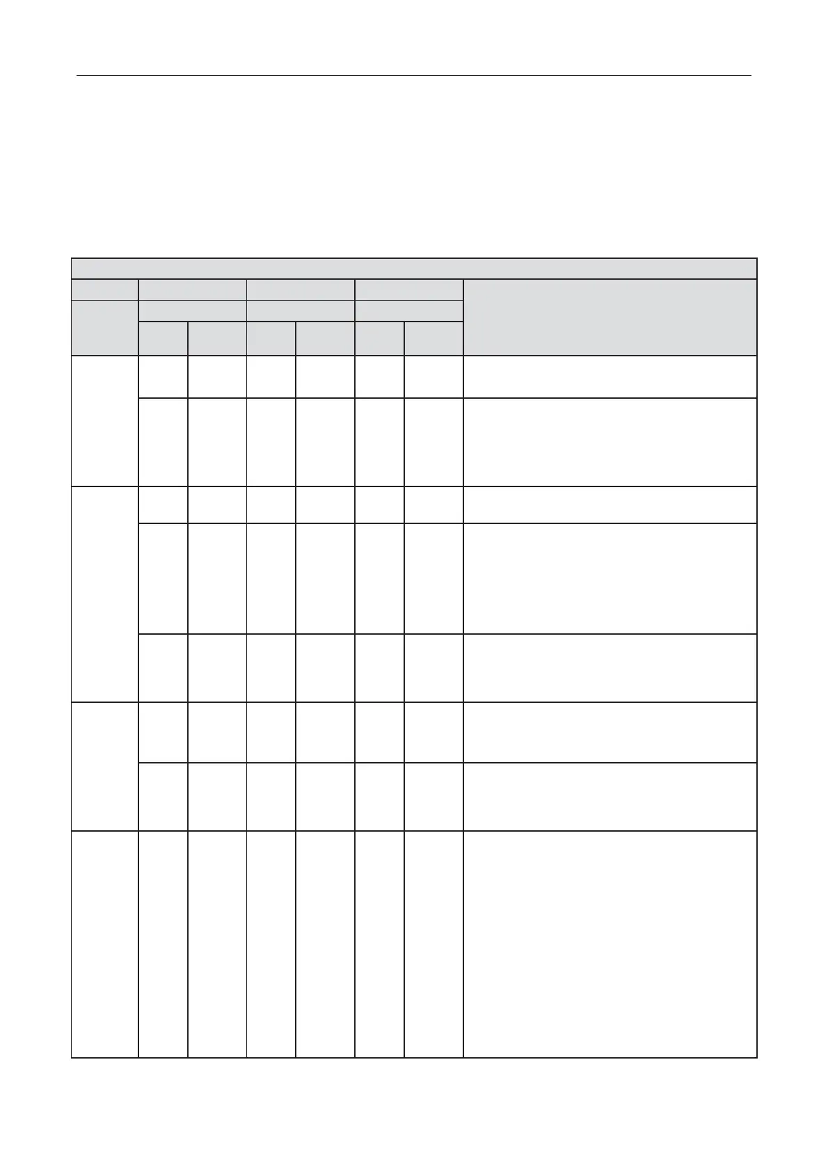
Stage process instruction for debugging
Code instruction and operation method
unit setting
A
No debugging status for system
Press SW7 button on main board for 5s to start
system debugging. The indicator on main board is
displayed as shown in the left. 2s later, it will enter
into next step determination.
02_ Address distribution
Address distribution for the system. 10s later, the
display is as below:
No main indoor unit. Display will be kept for 1min.
Within 1min, set the main i
ndoor unit through
debugging software. If notset the main indoor unit
by hand within 1min, the system will automatically
set the minimum IP address as the main indoor
unit.
The distribution for the system address is finished.
2s later,
it will enter into the next step
determination automatically.
03_Quantity
confirmation of
outdoor unit
Cofirmation process of system. 1s later, it will
enter into the next step automatically.
system. 2s later, it will
enter into the next step automatically.
04_Quantity confirmation of indoor
unit
LED3 displays quantity of indoor unit. The quanity
of indoor unit shall be confirmed by perform. If the
actural quantity of indoor unit is different from the
displayed quantity, cut off the power for indoor unit
and outdoor unit. Check whether the
communication wire for indoor unit is normal. After
that, put through the power and start debugging
from step 01. If the quantity o
f indoor unit is
SW7 button on main board to
confirm it. The display is as below after
confirmation:
 Loading...
