GREE DC Inverter Multi VRF System II Service Manual
19
z HBS interface: When HBS converter is under HBS communication mode, connect air
conditioner’s HBS data interface. HBS interface exhibits no polarity (This interface is not yet
available for Gree debugger and the monitoring software).
z RS485 interface: When RS485 converter is under RS485 communication mode, connect air
conditioner’s RS485 data interface. RS485 interface exhibits polarity and terminal A and B are
different.
3.3.2.4 Installation notice
z Install indoors. To avoid collision, it is suggested to place it in the monitoring room together with
the computer.
z No need of power supply. Power is supplied through computer’s USB interface.
3.3.3 Communication board
Communication board is mainly used for transferring data. It functions similar with a patching board.
Provided that units are far away from the monitoring computer, communication board can be used for
connection.
3.3.4 Communication cord
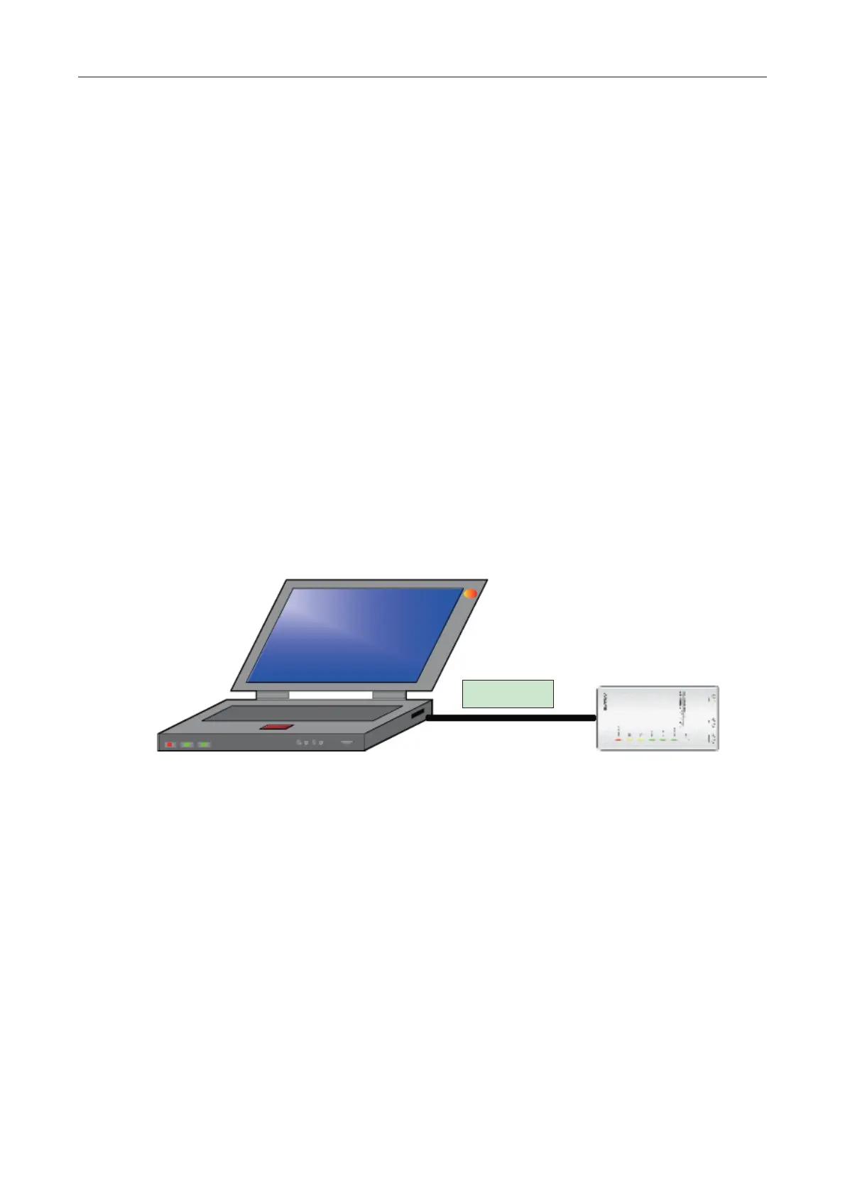
3.3.4.1 USB wire
z Connect USB wire with computer’s USB interface at one end and with the USB interface of USB
data converter at the other end, as indicated below:
3.3.4.2 Board Connection Wire
z There are 2 board connection wires supplied for the commissioning tool kits. One is 1 meter’s
long and the other is 5.5 meters’ long. They are only different in length. One end of the wire shall
connect with air conditioner’s communication interface and the other end shall connect with CAN
interface of Gree USB converter. As shown below, the wire can be connected to the
communication interface of outdoor unit or the communication interface of indoor unit:
 Loading...
