U-Match Series Duct Type Unit
35
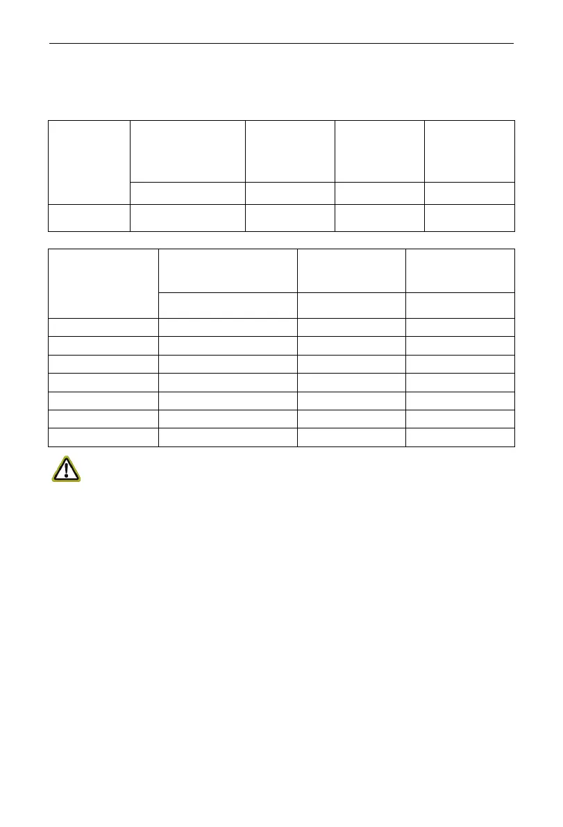
3.3.2 Electrical Parameters
3.3.2.1 Wire Specifications and Fuse Capacity
Model
Power Supply
Fuse
Capacity
Circuit
Breaker
Capacity
Sectional
Area of
V/Ph/Hz A A mm
2
Indoor Unit
220-240V ~50Hz
3.15 6 1.0
Model
Power Supply
Circuit Breaker
Capacity
Area of Power
V/Ph/Hz A mm
2
NOTICE:
①. Fuse is located on the main board.
②. Install a circuit breaker at every power terminal near the units (indoor and
outdoor units) with at least 3mm contact gap. The units must be able to
be plugged or unplugged.
③. Circuit breaker and power cord specifications listed in the above table are
determined based on the maximum power input of the units.
④. Specifications of power cords listed in the above table are applicable in a
working condition where ambient temperature is 40°C and multi-core
copper cable (e.g. YJV copper cable, with insulated PE and PVC sheath)
is protected by a conduit, and is resistant to 90°C in maximum (See IEC
60364-5-52). If working condition changes, please adjust the
specifications according to national standards.
 Loading...