60
Installation and Maintenance
Service Manual
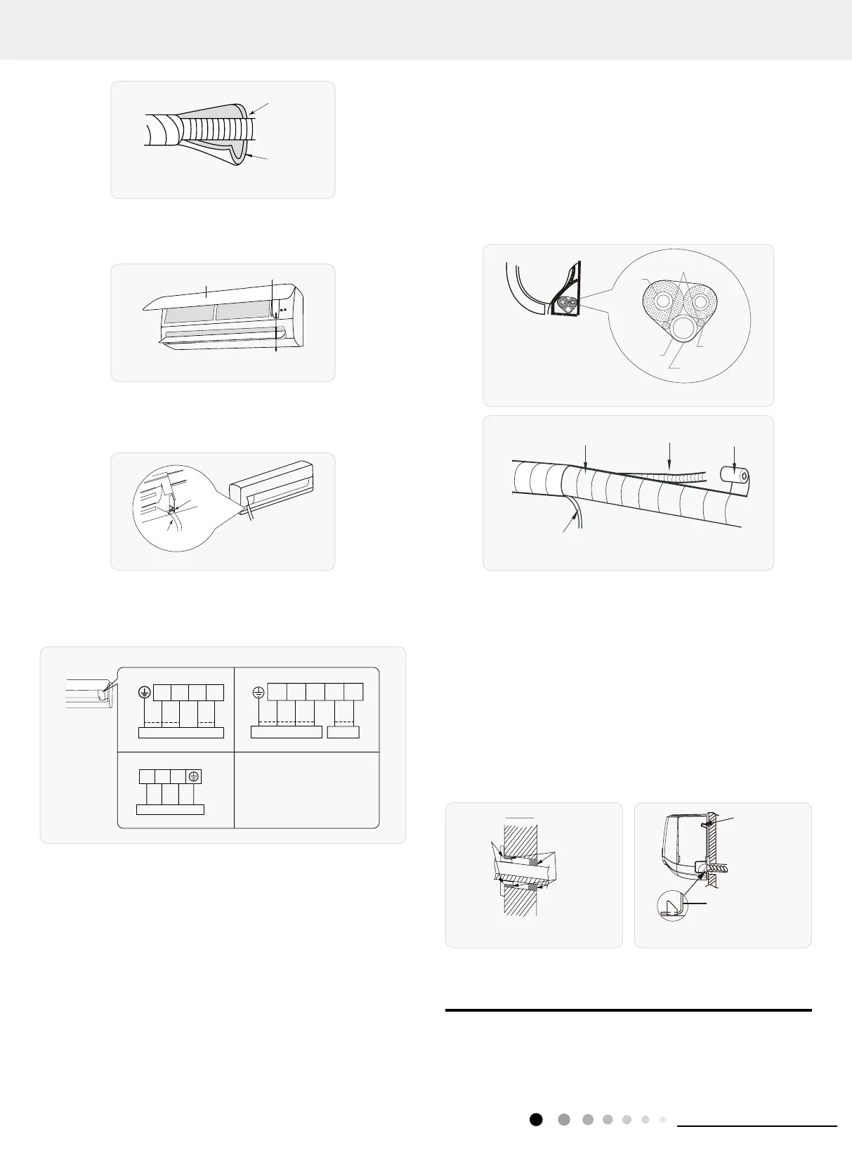
8. Bind up Pipe
(1) Bind up the connection pipe, power cord and drain hose with
the band. (As show in Fig.14)
(2) Reserve a certain length of drain hose and power cord for
installation when binding them. When binding to a certain degree,
separate the indoor power and then separate the drain hose. (As
show in Fig.15)
(3) Bind them evenly.
(4) The liquid pipe and gas pipe should be bound separately at
the end.
Indoor unit
Gas
pipe
Indoor and
outdoor power cord
Liquid
pipe
Drain hose
Band
Fig.14
Drain hose
Band
Connection pipe
Fig.15
Note:
(1) The power cord and control wire can't be crossed or winding.
(2) The drain hose should be bound at the bottom.
9. Hang the Indoor Unit
(1) Put the bound pipes in the wall pipe and then make them pass
through the wall hole.
(2) Hang the indoor unit on the wall-mounting frame.
(3) Stuff the gap between pipes and wall hole with sealing gum.
(4) Fix the wall pipe. (As show in Fig.16)
(5) Check if the indoor unit is installed firmly and closed to the
wall. (As show in Fig.17)
Indoor
Outdoor
Wall pipe
Sealing gum
Lower hook of
Fig.16
Fig.17
Note:
Do not bend the drain hose too excessively in order to prevent
blocking.
8.6 Installation of Outdoor unit
1. Fix the Support of Outdoor Unit(Select it according to the
actual installation situation)
Insulating pipe
Drain hose
Fig.10
7. Connect Wire of Indoor Unit
(1) Open the panel, remove the screw on the wiring cover and
then take down the cover. (As show in Fig.11)
Panel
Fig.11
(2) Make the power connection wire go through the cable-cross
hole at the back of indoor unit and then pull it out from the front
side. (As show in Fig.12)
Cable-cross
hole
Power connection
wire
Fig.12
(3) Remove the wire clip; connect the power connection
wiresignal control wire (only for cooling and heating unit) to the
wiring terminal according to the color; tighten the screw and then
x the power connection wire with wire clip. (As show in Fig.13)
Fig.13
(4) Put wiring cover back and then tighten the screw.
(5) Close the panel.
Note:
(1) All wires of indoor unit and outdoor unit should be connected
by a professional.
(2) If the length of power connection wire is insufcient, please
contact the supplier for a new one. Avoid extending the wire by
yourself.
(3) For the air conditioner with plug, the plug should be reachable
after nishing installation.
(4) For the air conditioner without plug, an air switch must be
installed in the line. The air switch should be all-pole parting and
the contact parting distance should be more than 3mm.
Note: The wiring connect is for reference only, please refer to the actual one.
07K ~ 24K(AFD) 24K(AFE)/28K
orange
N(1) 2 4 5
yellow-
black violet
green
blue
orange
Outdoor unit connectionOutdoor unit connection
yellow-
green
N(1)
2345
blue black
brown
violet
2
3
36K:
N(1)
yellow-
green
Outdoor unit connection
blue blackbrown
 Loading...