35
Installation and Maintenance
Service Manual
Model Air switch capacity Power cord
09/12K 10A 3G1.0
the following table. Air switch should be included magnet buckle
and heating buckle function, it can protect the circuit-short and
overload. (Caution: please do not use the fuse only for protect the
circuit)
8.5 Installation of Indoor Unit
1. Choosing Installation Iocation
Recommend the installation location to the client and then conrm
it with the client.
2. Install Wall-mounting Frame
(1) Hang the wall-mounting frame on the wall; adjust it in
horizontal position with the level meter and then point out the
screw xing holes on the wall.
(2) Drill the screw fixing holes on the wall with impact drill (the
specification of drill head should be the same as the plastic
expansion particle) and then ll the plastic expansion particles in
the holes.
(3) Fix the wall-mounting frame on the wall with tapping screws
and then check if the frame is rmly installed by pulling the frame.
If the plastic expansion particle is loose, please drill another xing
hole nearby.
Pay attention to dust prevention and take relevant safety
measures when opening the hole.
Fig.2
3. open piping hole
(1) Choose the position of piping hole according to the direction of
outlet pipe. The position of piping hole should be a little lower than
the wall-mounted frame,shown as below.(As show in Fig.1)
(2) Open a piping hole with the diameter of Φ55mm on the
selected outlet pipe position. In order to drain smoothly, slant the
piping hole on the wall slightly downward to the outdoor side with
the gradient of 5-10°.(As show in Fig.2)
Note:
Fig.1
300
300
55
55
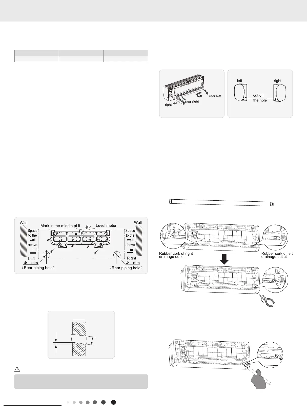
4. Outlet Pipe
(1) The pipe can be led out in the direction of right, rear right, left
or rear left.(As show in Fig.3)
(2) When selecting leading out the pipe from left or right, please
cut off the corresponding hole on the bottom case.(As show in
Fig.4)
(3) Selection of drainage outlet and drainage installation and
disassembly guide
●
Please determine the position of drainage outlet before
installation the drainage pipe.
●
Suggestion for selection of drainage outlet: there are no
mandatory requirements for the direction of the drainage pipe.
However, it's suggested to be same with the direction of liquid pipe
and gas pipe. Therefore, you are suggested to select the drainage
outlet which is close to the exit tube:
①
Take out the drainage pipe from the carton box.
②
Pull out the rubber stopper of drainage outlet with pliers or
other tools.
③
Install drainage pipe.
Hold the head of drainage pipe (20cm away from the drainage
pipe outlet) with hand and install it along the direction of drainage
outlet until you have head a sound.
Fig.3 Fig.4
 Loading...