37
Installation and Maintenance
Service Manual
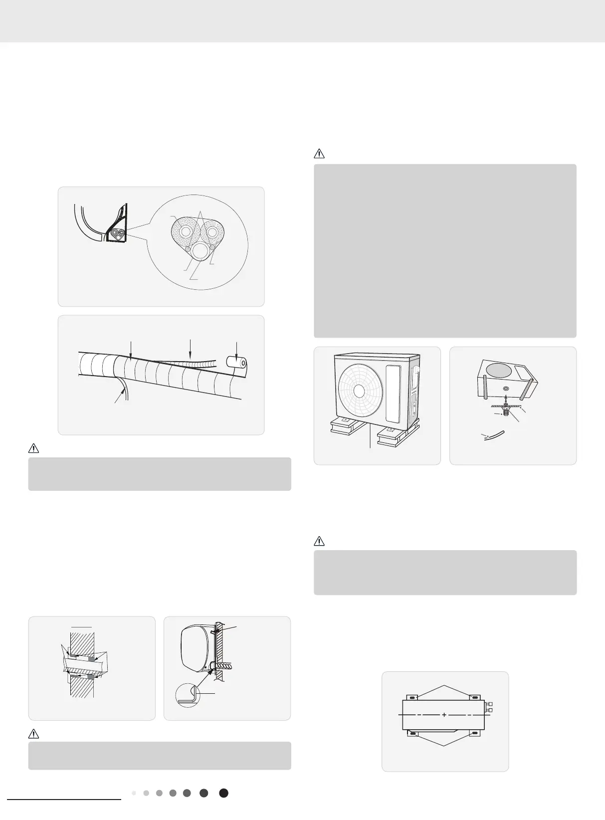
8. Bind up Pipe
(1) Bind up the connection pipe, power cord and drain hose with
the band.(As show in Fig.14)
(2) Reserve a certain length of drain hose and power cord for
installation when binding them. When binding to a certain degree,
separate the indoor power and then separate the drain hose.(As
show in Fig.15)
(3) Bind them evenly.
(4) The liquid pipe and gas pipe should be bound separately at the
end.
Indoor unit
Gas
pipe
Indoor and
outdoor power cord
Liquid
pipe
Drain hose
Band
Drain hose
Band
Connection pipe
Fig.14
Fig.15
(1) The power cord and control wire cant be crossed or winding.
(2) The drain hose should be bound at the bottom.
Do not bend the drain hose too excessively in order to prevent
blocking.
9. Hang the Indoor Unit
(1) Put the bound pipes in the wall pipe and then make them pass
through the wall hole.
(2) Hang the indoor unit on the wall-mounting frame.
(3) Stuff the gap between pipes and wall hole with sealing gum.
(4) Fix the wall pipe.(As show in Fig.16)
(5) Check if the indoor unit is installed firmly and closed to the
wall.(As show in Fig.17)
Note:
Note:
Indoor
Outdoor
Wall pipe
Sealing gum
lower hook of
Fig.16
Fig.17
(1) Take sufficient protective measures when installing the
outdoor unit.
(2) Make sure the support can withstand at least four times the
unit weight.
(3) The outdoor unit should be installed at least 3cm above the
oor in order to install drain joint.(As show in Fig.18)
(4) For the unit with cooling capacity of 2300W~5000W, 6
expansion screws are needed; for the unit with cooling capacity of
6000W~8000W, 8 expansion screws are needed; for the unit with
cooling capacity of 10000W~16000W, 10 expansion screws are
needed.
Note:
8.6 Installation of Outdoor unit
1. Fix the Support of Outdoor Unit(Select it according
to the actual installation situation)
(1) Select installation location according to the house structure.
(2) Fix the support of outdoor unit on the selected location with
expansion screws.
drain vent
chassis
2. Install Drain Joint(only for some models)
(1) Connect the outdoor drain joint into the hole on the chassis.
(As show in Fig.19)
(2) Connect the drain hose into the drain vent.
3. Fix Outdoor Unit
(1) Place the outdoor unit on the support.
(2) Fix the foot holes of outdoor unit with bolts.
(As show in Fig.20)
Fig.18
Fig.19
Fig.20
at least 3cm above the floor
●
As for the shape of drainage joint, please refer to the current
product. Do not install the drainage joint in the severe cold area.
Otherwise,it will be frosted and then cause malfunction.
Note:
 Loading...