14
for North America
CONTROL
CONTROL
1 Units’ Control
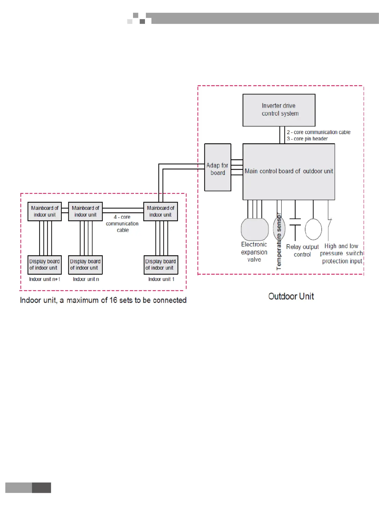
1.1 Schematic diagram of units’ control
Air conditioning units can be divided into indoor unit and outdoor unit. A maximum of 16 sets of indoor units
can be connected to an outdoor unit. 2-core (3-core pin header) communication cable is used for the connection
between indoor unit and outdoor unit. Indoor unit is connected to display board via 4-core communication cable. In
engineering installation, address dial-up of the display board and the mainboard of indoor unit shall be dialed. The
address dial-up of the mainboard of indoor unit must be identical with that of the display board of the same indoor
unit. Address dial-up of different indoor unit must vary. Multi VRF indoor unit is applicable to all digital or inverter
outdoor units.
Controller of outdoor unit falls into two categories in terms of its function, i.e. main control system and
inverter drive control system
Photovoltaic Direct-driven VRF
 Loading...