68
for North America
Photovoltaic Direct-driven VRF
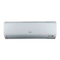
(3) Wall Mounted Type IDU
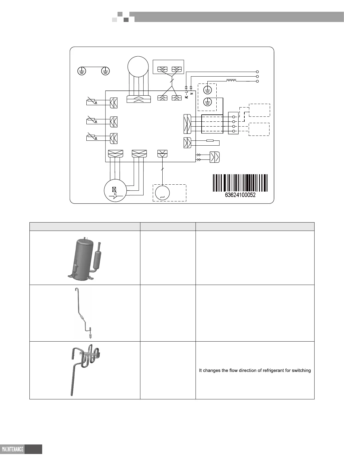
GMV-N07G/A3A-D(U)~GMV-N24G/A3A-D(U):
AP1
D1
D2
XT 1
HE AT - L1
RT 1
15K
RT 2
20K
CN 22
CN 31
X1
CN 3
CN 25
M
M2
HE AT - N1
Motor
POWER
CN 12
CN 6
WH
BN
IND OOR UNI T
5
H1
RD
M1
RT 4
20K
CN 2
( ROOM )
( PI PE-I N)
( PI PE-ON )
CN 7
BK
WH
BN
CN 20( FB)
Electroni c expansion valve
EKV
22K
H2
Evaporator
RD
GN
L1
L2
G
Ou t t emp. sensor
I n temp. sensor
Envir onment
t emp.sens or
Steppi ng
Mot or
RD
BN
BK
OG
Di spl ay
RE CEI VER AND
DI SPLAY BO AR D
CN 41
CN 42
13
WH
WH
( COM - OUT )
( Humi d)
G
G
Electri cal boxEvaporator
I n/outdoor
unit
Wi red
control ler
G
YE GN
YE GN
BK
4 Removal of Parts
4.1 Key parts
Photo Name Function
compressor
Core part of air conditioning system. It sucks low
temperature and low pressure gas, compress it to
high temperature and high pressure gas, and then
discharge it.
Electronic expansion
valve
Throttling device. It transforms high pressure
refrigerant liquid into low pressure steam.
4-way valve
between cooling and heating.
 Loading...