65
for North America
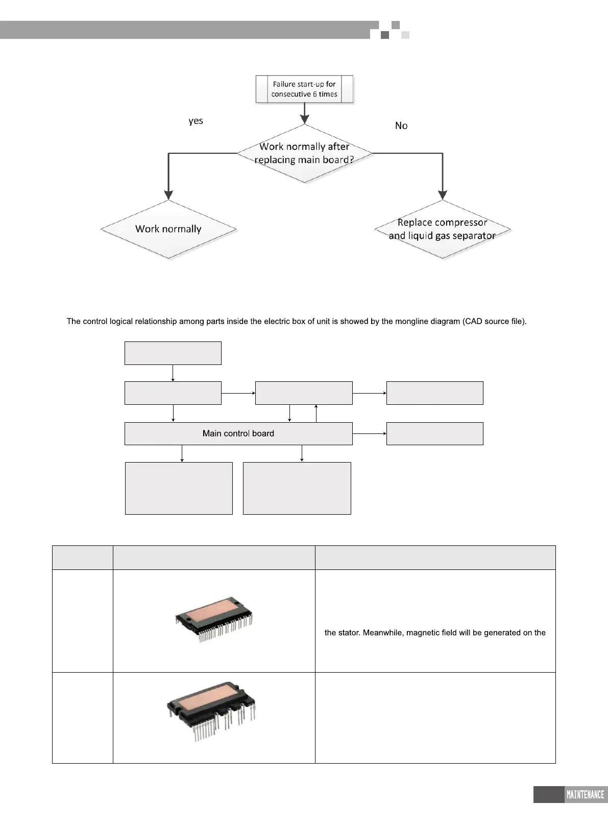
(7) Failure start-up
3.2 Main electric parts
Name Photo Function introduction
IPM Module
There are three complemental IGBT tube inside the IPM
module. They are controlled by PWM wave and then bring
the pressure of DC bus bar to different stator windings of
compressor at different stage, and then generate current on
stator winding, and push the operation of rotor and then drive
compressor to operate.
PFC module
Four diodes and two MOS pipe are intergrated inside the
PFC module. It will transform AC input power into DC power.
Meanwhile, MOS pipe is controlled by PWM wave. Pressure
will be increased by induction.
3 Power Distribution of Unit
3.1 Power distribution of unit
The main loop is showed by bold line (line width: 1mm); the control loop is showed by slim line (line width: 0.2mm).
Filter plate Drive board
Compressor
Fan
Power wiring board
4-way valve,by-pass
valve,electric heating belt
and control signal
Temperatuer sensor,electric
expansion valve,high
pressure and low pressure
switch and so on
(
Bold line is the power line and the slim line is the control line
)
Photovoltaic Direct-driven VRF
 Loading...