50
Air to Water Heat Pump
Service Manual- Versati II Series
INSTALLATION
T-SENSOR3 CN12 terminal of temperature sensor3
T-SENSOR4 CN13 terminal of temperature sensor4
T-SENSOR5 CN14 terminal of temperature sensor5
T-SENSOR6 CN15 terminal of temperature sensor6
DOOR-C CN23 Door detection input
OVC-HEAT3 CN28 e-heater of water tank adhesion-proof protection detector
OVC-HEAT1 CN26 e-heater of indoor unit1 adhesion-proof protection detector
OVC-HEAT2 CN27 e-heater of indoor unit2 adhesion-proof protection detector
IN-SW CN25 detection input of water ow switch
COM-MANUAL CN6 connect the wired controller
COM-OUT CN5 connect to outdoor unit
TR-OUT1 CN2 transformer output 1
TR-OUT2 CN3 transformer output 2
TR-IN CN1 220V input of transformer
CN30 CN30 heavy-current interface of end controller
CN31 CN31 heavy-current interface of end controller
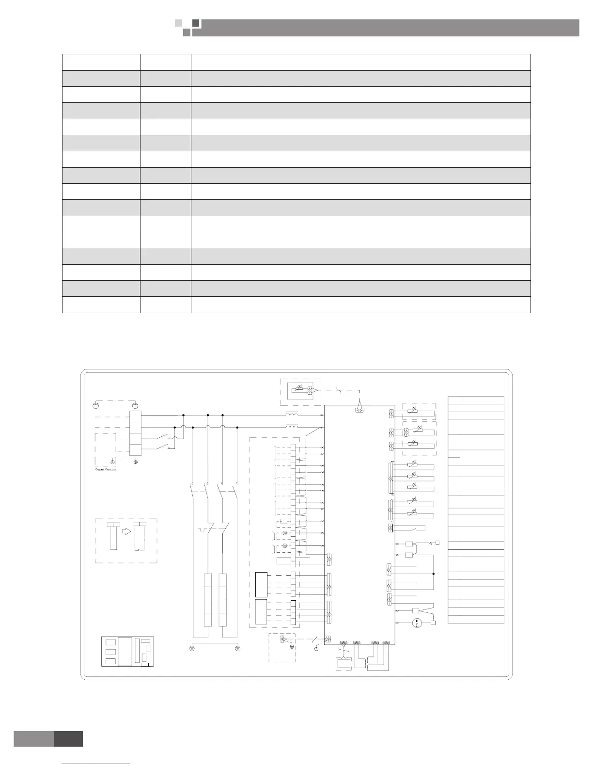
2�3 Electric Wiring Design
2.3.1 Wiring Diagram: Indoor Unit
GRS-CQ12Pd/NaB-K(I) ,GRS-CQ14Pd/NaB-K(I),GRS-CQ16Pd/NaB-K(I):
2
Specification:
1
.
If there is gate control function,
pull out the leading wire 50 on
terminal boards between19 and 20
and then connect the
Gate-controller
.
51
HT1
KM3-4
BU
Indoor Unit
N
L
5
AP1
RT8
RT4
RT5
XT2
XT2
3
12
11
14
13
KM1-6
KM2-6
15
16
CN28
CN27
CN26
KM3-6
AC contactor
KM4
0
1
0
1
18
19
17
1
0
KM1
KM2
21
22
KM3
14
X17X18X16
26
25
48
47
46
45
44
43
4241
X13
50
49
3
1
X19
CN23
HL2
HL1
X15
KM4
X14
20
19
18
17
16
15
14
13
Thermostat1
(WP65A-R
)
HT1
Main Board
AP
Water-tank
3
20K
50K
50K
20K
20K
20K
20K
20K
Main Board Only For RT9
Water flow switch
SW
AP2
2
CN14
53
52
CN66
PE
PE
OUTDOOR
UNIT
CN5
RD
BK
XT2
39
38
37
36
35
34
XT2
33
32
31
30
8
3-way
valve1
2-way
valve2
2-way
valve1
N
L2(ON)
L1(OFF)
L1(OFF)
N
L2(ON)
N
L1(OFF)
L2(ON)
N
L2(ON)
L1(OFF)
12
11
10
9
8
7
6
5
4
3
2
1
4
6
N(2)
1
L
TC
6
4
N
XT1
KM1
6
4
KM2
N
CN2
CN1
CN3
CN10
CN12
CN11
CN13
CN15
X5X6
X7
X8
X9X10
X11
X12
CN25
RT1
RT2
RT3
RT7
RT6
AP
(AC-L)
POWER
N
1
EH1
EH2
CN6
4
Water tank Auxiliary
electric heater
CODE
NAME
KM1
KM2
KM3
M
EH1~2
Auxiliary electric heater
1,2 AC contactor
Water PUMP
Auxiliary electric
heater 1
,
2
heater AC contactor
Water tank
XT1,2,3
Terminal block
1
3
4
7
9
SW
RT1
RT2
RT3
RT5
RT6
RT7
RT4
Water-tank temp sensor2
Water-tank temp sensor1
RT8
RT9
Water- out temp sensor
Remote Air temp sensor
AP
KM1
KM2
KM3
XT1
TC
21
22
23
24
25
26
27
28
CN30
1
74
1
CN31
XT3
Thermostat
COOL
HEAT
N
L
(230V)
(24V)
L
N
Thermostat
COOL
HEAT
CN1
RT9
AP2
15K
2.The wires in the imaninal frames
are connected by the consumer.
3.power supply for Thermostat:If it is
230V AC,please connect Terminal
block(xt3) 21.22.23.24;If it is 24V
AC, please connect Terminal
block(xt3) 25.26.27.28.
54
55
56
57
58
59
60
61
XT3
HT2
62
1920
50
Gate-controller
20 19
XT2XT2
HT2
Thermostat2
(WP95A-R)
PE PE
8
2
WH
2
8
663
64
8
2
KM3
65
HT1
Running
indicating lamp
Error
indicating lamp
Communication line
Display
board
Client water pump
Plate heat exchanger
water-out temp sensor
Plate heat exchanger
water-in temp sensor
Liquid line temp sensor
Gas line temp sensor
Auxiliary electric heater
water-out temp sensor
Client water pump
AC contactor
Other thermal
PEPE
PEPE
TC
Transformer
Other
thermal
Auxiliary electric
 Loading...