56
Air to Water Heat Pump
Service Manual- Versati II Series
INSTALLATION
4
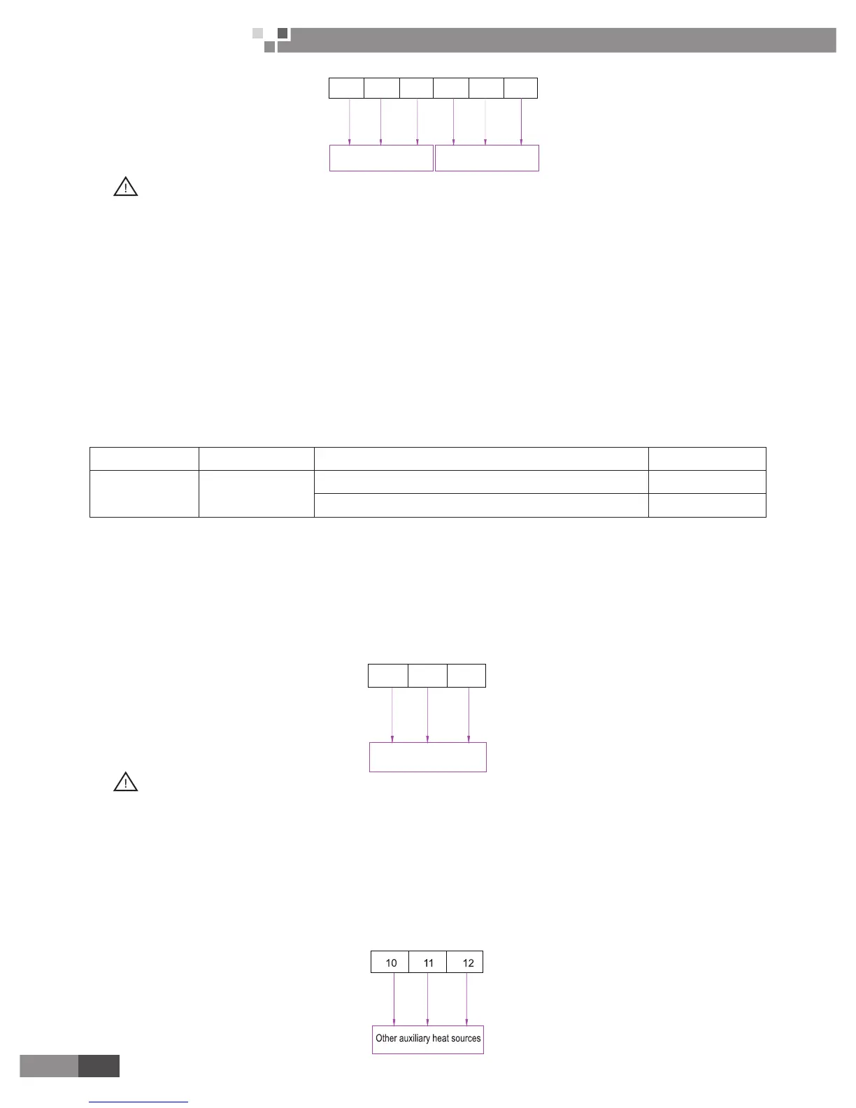
321
OFF
NC
2 way value 1
2 way value 2
NC
NO
NO
OFF
ON
ON
N
N
N
N
5
6
WARING!
①
Normal Open type should be connected to wire (NO) and wire (N)for valve closing in cooling mode.
②
Normal Closed type should be connected to wire (NC) and wire (N)for valve closing in cooling mode.
(NO) : Line signal (for Normal Open type) from PCB to 2-way valve
(NC) : Line signal (for Normal Closed type) from PCB to 2-way valve
(N) : Neutral signal from PCB to 2-way valve
The 2-way value 2 is reserved without any control program. At the eld installation, it should be wired at the
terminal board of the 2-way valve 1.
Other auxiliary heat sources are allowed for the equipment and controlled in such a way that the mainboard
will output 230V strong signals when outdoor temperature is lower than the set point for startup of the auxiliary
heat source.
2.3.8 3-Way Valve
3-way valve is required to operate sanitary water tank. Role of 3-way valve is ow switching between under
oor heating loop and water tank heating loop.
General Information
Type Power Operating Mode Supported
SPDT
3-wire
230V 50Hz ~AC
Selecting “Flow A” between “Flow A” and “Flow B” Ye s
Selecting “Flow B” between “Flow B” and “Flow A” Yes
(1) SPDT = Single Pole Double Throw. Three wires consist of Live1 (for selecting (for selecting Flow B),
and Neutral (for common).
(2) Flow A means ‘water ow from the indoor unit to under oor water circuit.’
(3) Flow B means ‘water ow from the indoor unit to sanitary water tank.’
How to Wire 3-Way Valve:
Follow below procedures Step 1 ~ Step 2.
Step 1. Uncover front cover of the indoor unit and open the control box.
Step 2. Find terminal block and connect wire as below.
WARING!
①
3-way valve should select water tank loop when electric power is supplied to wire (OFF) and wire (N).
②
3-way valve should select under oor loop when electric power is supplied to wire (ON) and wire (N).
(OFF) : Line signal (Water tank heating) from PCB to 3-way valve
(ON) : Line signal (Under oor heating) from PCB to 3-way valve
(N) : Neutral signal from PCB to 3-way valve
2.3.9 Other Auxiliary Heat Sources
Other auxiliary heat sources are allowed for the equipment and controlled in such a way that the mainboard
will output 230V when outdoor temperature is lower than the set point for startup of the auxiliary heat source.
 Loading...