Home
Gree
Heat Pump
Versati II Series
Gree Versati II Series User Manual
5
of 1
of 1 rating
97 pages
Give review
Manual
Specs
To Next Page
To Next Page
To Previous Page
To Previous Page
Loading...
52
Air to W
ater Heat Pump
Service Manual- V
ersati II Series
INSTALLATION
SXVD200LCJ/A-M, SXVD200LCJ2/A-M, SXVD300LCJ/A-M, SXVD300LCJ2/A-M,SXVD200LC
J/A-H,
SXVD200LCJ2/A-H, SXVD300LCJ/A-H, SXVD300LCJ2/A-H:
WP95A-R
(WP85A-R)
PE
PE
PE
PE
Thermostat1T
hermostat2
Heater
54
56
Table of Contents
Default Chapter
2
Table of Contents
2
Product
5
Models List
5
Nomenclature
5
1�1 Main Unit
5
1�2 Water Tank
5
Function
6
2�2 Water Tank
6
3�1 Cooling
6
3�2 Heating
6
3�3 Water Heating
6
3�4 Cooling +Water Heating
6
3�5 Heating+ Water Heating
6
3�6 Emergency Mode
6
3�7 Quick Water Heating
7
3�8 Holiday Mode
7
3�9 Forced Operation Mode
7
3�10 Silent Mode
7
3�11 Disinfection Mode
7
3�12 Weather-Dependent Heating Mode
7
Outdoor Unit
8
4�1 Product Data at Rated Condition
8
Indoor Unit
9
4�2 Operation Range
10
4�3 Electrical Data
11
Piping Diagram
12
Units Control
14
Operation Flowchart
14
Main Logic
15
2�1 Defrosting Mode
15
2�2 Water-Side Auto Anti-Freezing in Winter
15
2�3 Control of Heating Tape on Chassis
15
2�4 Control of Fan
15
2�5 Control of Compressor
15
2�6 Control of Electric Expansion Valve
15
Wired Controller
16
3�1 Dimension
16
3�2 Function
16
External View
16
Standby Page and Homepage
17
3�3 Operation Instruction
18
Indicating Leds
18
Keys
18
On/Off
18
Control State
20
Fast Hot Water
20
Mode
20
T-Water Ctrl
20
Auto Mode
21
Holiday Release
21
Quiet Mode
21
Quiet Timer
21
Sanitize
22
Weekly Timer
22
Clock Timer
24
Temp Timer
25
Floor Debug
26
Emergency Mode
27
Thermostat
27
IDU Heater
28
Other Heater
28
Tank Sensor
28
Underpan Heater
28
Address
29
Doorguard
29
Parameter Setting (Parameter Set)
29
User Parameter Setting
29
Status View
31
View
31
Viewable Components
31
Parameter View
32
Error View
33
Version View
34
Clock Setting
35
General Set
35
Control Wiring Design
36
3�4 Precautions
36
Installation Instruction
36
Key Lock
36
Installation of Units
38
1�1 Installation Positions
38
1�2 Matters Need Attention
38
Installation Positions of Indoor
38
Installation Positions of Outdoor
38
Installation Positions of Water Tank
38
1�3 Dimension Data and Installation Guide
39
Install Process of Indoor Unit
40
Installation Measure
41
Installation of Insulated Water Tank
41
Precautions on Installation of Indoor Unit
41
Outline Dimension and Parameter of Water Tank
42
Connection of Waterway System
43
Electric Wiring
44
Wiring Principle
44
1�4 Installation Clearance Data
45
Water Volume and Pump Capacity
45
Adjusted Is as Follows
46
Water Volume and Expansion Vessel Pressure
46
Filling of Refrigerant
47
1�6 Connection of Pipeline
48
Connection of Outlet Pipe for Indoor & Outdoor Unit
48
Installation of Protective Layer on Connection Pipe
48
Electric Wiring Work
50
2�1 Wiring Principle
50
2�2 PCB Outline
51
Wiring Diagram: Indoor Unit
53
2�3 Electric Wiring Design
53
Wiring Diagram: Outdoor Unit
54
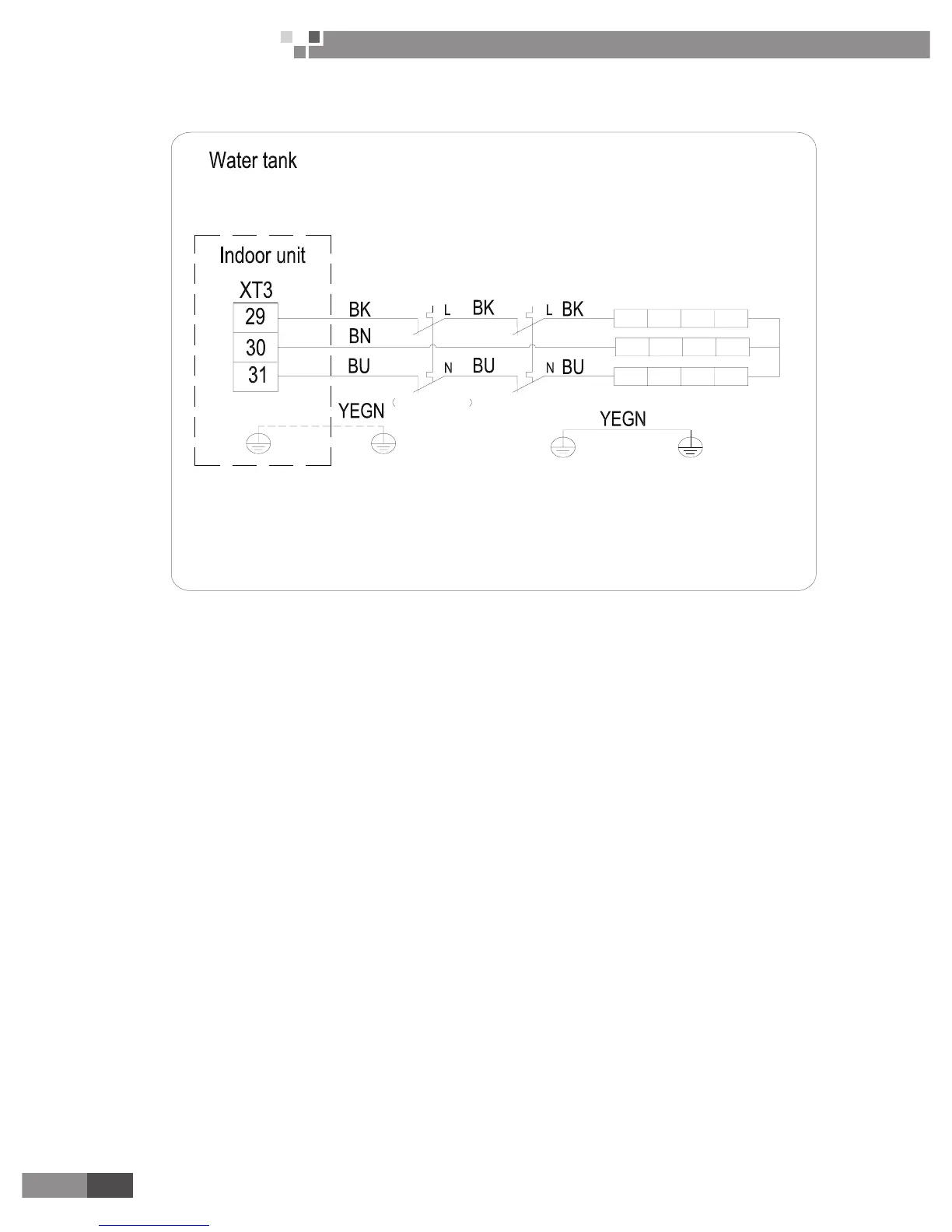
Wiring Diagram: Water Tank
54
Wiring Diagram: Indoor and Outdoor Unit
56
Terminal Board Information
57
Connecting with External Electric
58
2-Way Valve
58
3-Way Valve
59
Other Auxiliary Heat Sources
59
Gate-Controller
60
Remote Air Temperature Sensor
60
How to Wire Thermostat
61
Units Maintenance
63
Error Code List
63
Complete Unit Code
63
Drive Failure Code
66
Flow Chart of Troubleshooting
67
Comp High-Pressure Protection E1
67
Comp Low- Pressure Protection E3
68
DC Fan Error EF
69
Overload Proection of Compressor or Driver Error E5
69
Communication Malfunction E6
70
Temperature Sensor Error
70
3�1 Diagnosis Flowchart of Driving of Single-Phase Unit and Three-Phase Unit
71
Indoor Capacity Switch Error
71
DC Busbar Over-Voltage/Under-Voltage Protection
72
IPM or PFC Over-Temperature Protection
72
Compressor Startup Failure
73
Drive-To-Main-Control Communication Error
73
Charging Circuit Error
74
Compressor Current Protection/Motor Desynchronizing
74
IPM Protection, Phase Loss
74
Disassembly and Assembly Procedure of Main Parts
75
Front Panel Assy
82
Electric Box Assy
83
Water Pump and Water Flow Switch
83
Electric Heater, Automatic Air Outlet
84
Expansion Tank
84
Plate-Type Heat Exchanger
84
5�1 Outdoor Exploded View and Part List
85
5�2 Indoor Exploded View and Part List
87
5�3 Water Tank Exploded View and Part List
89
Exploded View
93
5
Based on 1 rating
Ask a question
Give review
Questions and Answers:
Need help?
Do you have a question about the Gree Versati II Series and is the answer not in the manual?
Ask a question
Gree Versati II Series Specifications
General
Brand
Gree
Model
Versati II Series
Category
Heat Pump
Language
English
Related product manuals
Gree Versati II+
18 pages
Gree VERSATI III Series
55 pages
Versati III GRS-CQ4.0PdG/NhH2-E
58 pages
Gree VERSATI SERIES
158 pages
Gree Vita GWH07ATA-D3DNA3A/I
24 pages
Gree Vita GWC09ATCXB-D3DNA3A/I
24 pages
Gree VIREO GEN3 3VIR09HP115V1A
101 pages
Gree Vita GWC12ATCXB-D3DNA1C/O
24 pages
Gree Vita GWH12ATCXB-D3DNA1C/O
24 pages
Gree Vita GWH18ATDXD-D3DNA3A/I
24 pages
Gree Vita GWH18ATDXD-D3DNA1A/O
24 pages
Gree Vireo GEN3 3VIR12HP230V1AH
22 pages
 Loading...