English (GB)
11
Set the switches 1 to 10 as follows:
• Switches 1, 2 and 3, application type:
When the DIP switch setting is changed, the controller must
be switched off for at least 1 minute!
•Switch 4, starting delay and automatic test run (only in the
case of battery back-up):
When the DIP switch setting is changed, the controller must
be switched off for at least 1 minute!
• Switches 5, 6 and 7, stop delay:
When the DIP switch setting is changed, the controller must
be switched off for at least 1 minute!
•Switch 8:
When the DIP switch setting is changed, the controller must
be switched off for at least 1 minute!
•Switch 9, automatic alarm resetting:
When the DIP switch setting is changed, the controller must
be switched off for at least 1 minute!
•Switch 10, automatic restarting:
When the DIP switch setting is changed, the controller must
be switched off for at least 1 minute!
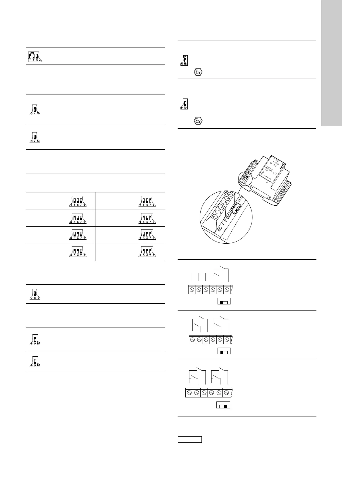
AC/DC selector:
The AC/DC selector switch for electrodes and/or float switches is
placed as shown in fig. 9.
Fig. 9
This setting determines the actual application type
(3 float switches, pages 39 and 40).
At this setting, the start-up is delayed within the range
from 0 to 255 sec. (random) after the electricity supply
has been switched on when the liquid level is
sufficiently high.
Automatic test run carried out every 24 hours.
After the electricity has been switched on, the pump will
start immediately when the liquid level is sufficiently
high.
No automatic test run.
The stop delay is the time from the stop signal is given until the
pump is stopped.
It must be ensured that the pump is not running dry.
0 sec. 60 sec.
15 sec. 90 sec.
30 sec. 120 sec.
45 sec. 180 sec.
Switch 8 has no function in connection with the actual
application (3 float switches, pages 39 and 40), but this
setting must be maintained!
This setting ensures automatic resetting of alarm
signals to external alarm devices and the built-in
buzzer. However, an alarm signal will only be reset if
the cause of the fault no longer exists.
At this setting, the alarm signal must be reset manually
by means of the reset button (the reset button is
described in section 5.5).
This setting enables automatic restarting after the PTC
resistance/thermal switch of the motor has cut out the
pump. Restarting will not be carried out until the motor
has cooled to normal temperature.
When the pump connected is used in an explosion
hazard area, switch 10 must not be in this position!
At this setting, the pump must be restarted manually after
the PTC resistance/thermal switch of the motor has cut
out the pump. To restart the pump, push the ON-OFF-
AUTO selector switch into position OFF for a short period
(the ON-OFF-AUTO selector switch is described in
section 5.5).
When the pump connected is used in an explosion
hazard area, switch 10 must be in this position!
TM02 5747 3902
Operation with electrodes and
float switches:
Selector switch in position AC:
It is possible to connect
3 electrodes (1 as reference
electrode) and 2 float switches.
The controller transmits a
13-18 VAC signal.
Operation with float switches:
Selector switch in position AC:
It is possible to connect 4 float
switches.
The controller transmits a
13-18 VAC signal.
Operation with float switches:
Selector switch in position DC:
It is possible to connect 4 float
switches.
Cables of up to 100 metres can be
connected between the controller
and the float switches.
The controller transmits a 12 VDC
signal.
If the distance between the controller and pit
exceeds 20 metres, it is not advisable to use
electrodes as problems with the signal values sent
back to the controller may arise.
In such cases, it is recommended to use float
switches.
AC 1 2
13-18 VAC
0 V
AC
DC
G3 4
AC 1 2
13-18 VAC
0 V
AC
DC
G3 4
 Loading...