3. Installation
28 PNEG-900 Series 2000 Autoflow Fan/Heater and Control Installation Instructions
Drying Chamber Low-Level Rotary Switch Installation
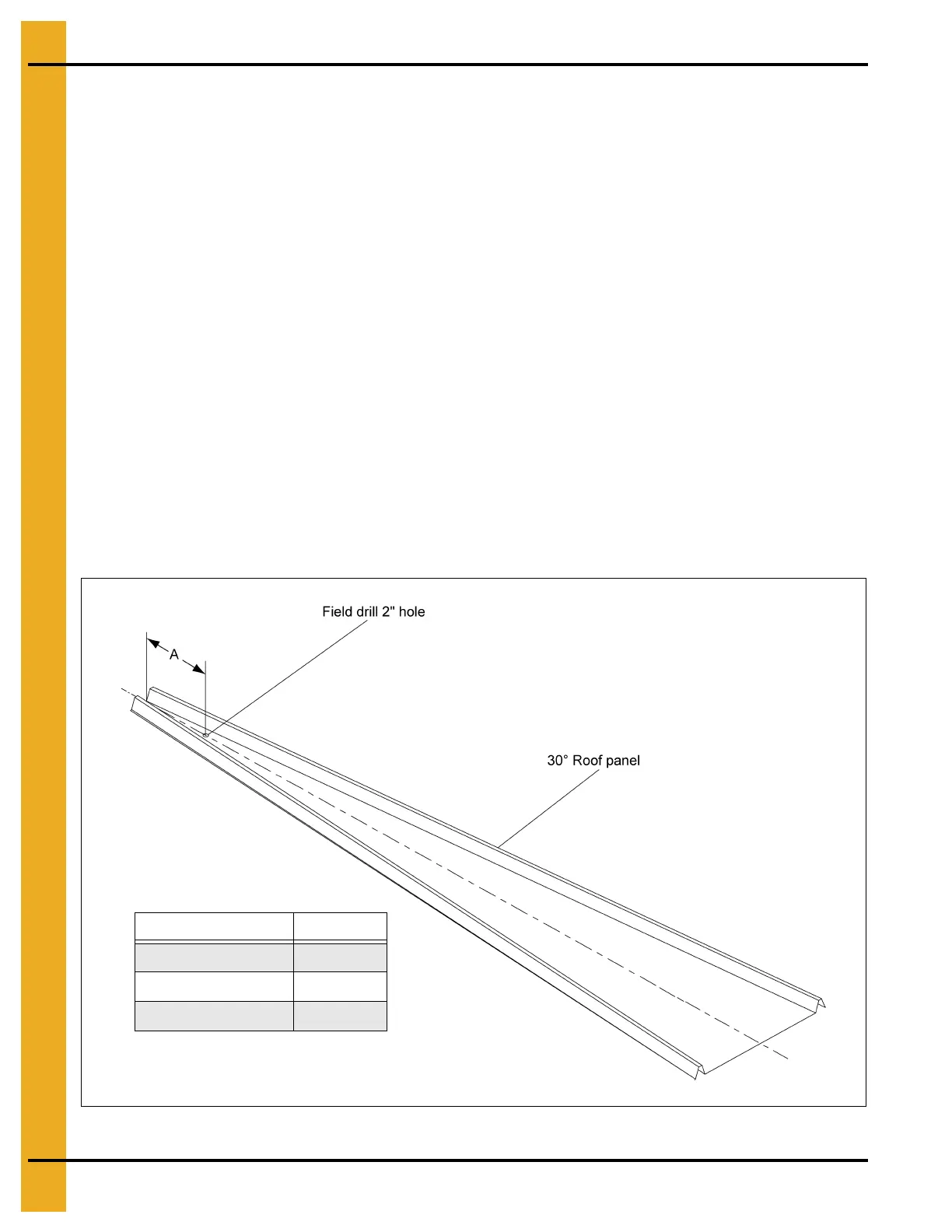
1. Drill a 2" diameter hole through the roof panel at the location shown in Figure 3T. See component
placement on Page 11 for proper placement in relation to fill auger.
2. Use the mounting plate as a pattern and drill four (4) 3/8" holes through the roof panel at the switch
location so the plate can be bolted to the roof.
3. Attach the flex coupling to the rotary switch power pack using a roll pin.
4. Apply teflon tape or pipe sealant (not included) to the rotary switch power pack threads and thread
the rotary switch power pack into the mounting plate coupling.
5. Make sure that the conduit hole is at right angles with the roof panel ribs or facing towards the eave.
6. Caulk the underside of the mounting plate and on all sides of the 2" hole.
7. Bolt the assembly to the roof panel.
8. Attach the shaft extension according to Figure 3U on Page 29.
9. Apply teflon tape or pipe sealant (not included) to the shaft guard.
10. Thread to underneath side of mounting plate.
11. Add the 1/4" drilled coupling to the shaft extension using the cotter pin.
12. Attach the 1 vane paddle to the flex coupling as shown in Figure 3U on Page 29.
Figure 3T
Top Dry Bin Diameter “A”
18'-24' 23-1/2"
27' and 30' 19"
36' 31"
 Loading...


