4. Electrical Power Supply
44 PNEG-900 Series 2000 Autoflow Fan/Heater and Control Installation Instructions
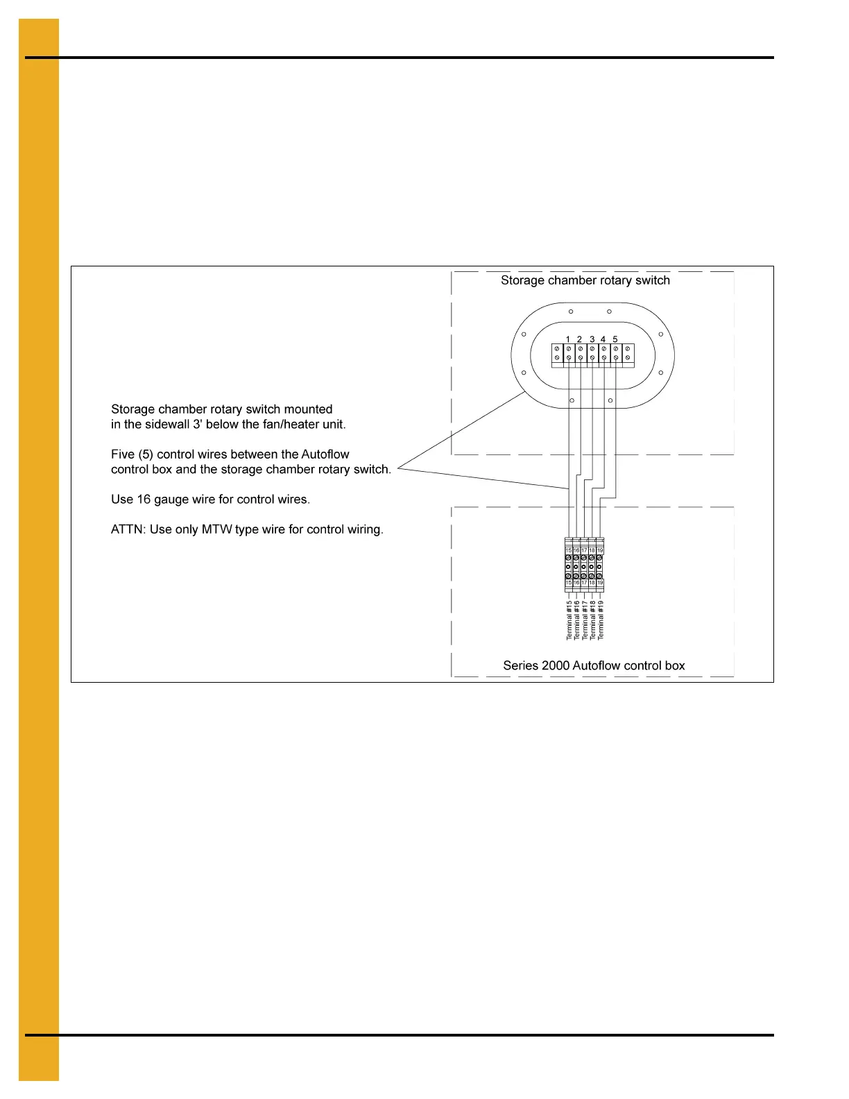
Autoflow to Storage Chamber Rotary Switch Interconnect
The 110V AC rotary switch located in the storage tank is used to inform the computer on the availability
of wet grain. The Storage Chamber Rotary switch is mounted 3' below the fan/heater unit(s). The Storage
Chamber Rotary switch use 110V AC to power the motor and 12V DC+ to switch a signal back to
the computer.
To wire the storage chamber rotary switch to the Autoflow control box do the following:
1. Run five (5) control wires from the Autoflow control box to the Storage Chamber Rotary switch.
2. Connect the wires as shown in Figure 4H.
Figure 4H
Autoflow to Drying Chamber Rotary Switches Interconnect
The three (3) 110V AC rotary switches located in the drying chamber are used to inform the computer on
the location of grain in the drying chamber. The rotary switch with the shortest extension is the Drying
Chamber Overflow Rotary switch. It is used as a safety in the event the Chamber High-Level Rotary switch
fails. The rotary switch with the longest extension is the Drying Chamber Low-Level Rotary switch. It is
used to inform the computer when the peak has been covered with grain so the drying process can begin;
and, will shut the dryer down if the drying chamber empties unexpectedly. The third rotary switch is the
Drying Chamber High-Level Rotary switch. It is used to inform the dryer when the drying chamber is full.
The Drying Chamber Rotary switches us 110V AC to power the motor and 12V DC+ to switch a signal
back to the computer. The 110V AC, 110V N and the 12V DC+ wires can be jumped from rotary switch to
rotary switch to lessen the wires needed.
To wire the Drying Chamber Rotary switches to the Autoflow control box do the following:
1. Run six (6) control wires from the Autoflow control box to the Drying Chamber Rotary switches.
2. Connect the wires as shown in Figure 4I on Page 45.
 Loading...


