ERROR CODES & PROBLEM SOLVING
PAGE 40
ENGLISH
Checking the Up/Down or Left Stepper Motor
Step 1
Disconnect the Up/Down or Left Stepper Motor plug from
the control board connector for this test. Failure to do so may
provide inaccurate readings.
Step 2
There are ve wire colors; red, orange, yellow, purple and
blue. The resistance between the red wire and any other wire
should be 200 to 300Ω approximately.
Step 3
Re-seat the plug on the connector at the conclusion of the
test.
Checking the Indoor DC Fan Motor
Step 1
Disconnect the DC Fan Motor plug from the control board
connector for this test. Failure to do so may provide
inaccurate readings.
Step 2
Refer to the chart shown below for plug pin combinations and
resistance values.
Note: Test is polarity sensitive, adhere to probe placement as
shown in chart.
Red Test Lead
Black
Test
Lead
Pink X X Black White Blue Yellow
Pink X X 15.27Meg 15.46 Meg Innity 15.85 Meg
X X X X X X
X X X X X
Black 108.2K Innity 241.8K
White Innity 349.5K
Blue 5.14 Meg
Yellow
Step 3
Re-seat the plug on the connector at the conclusion of the
test.
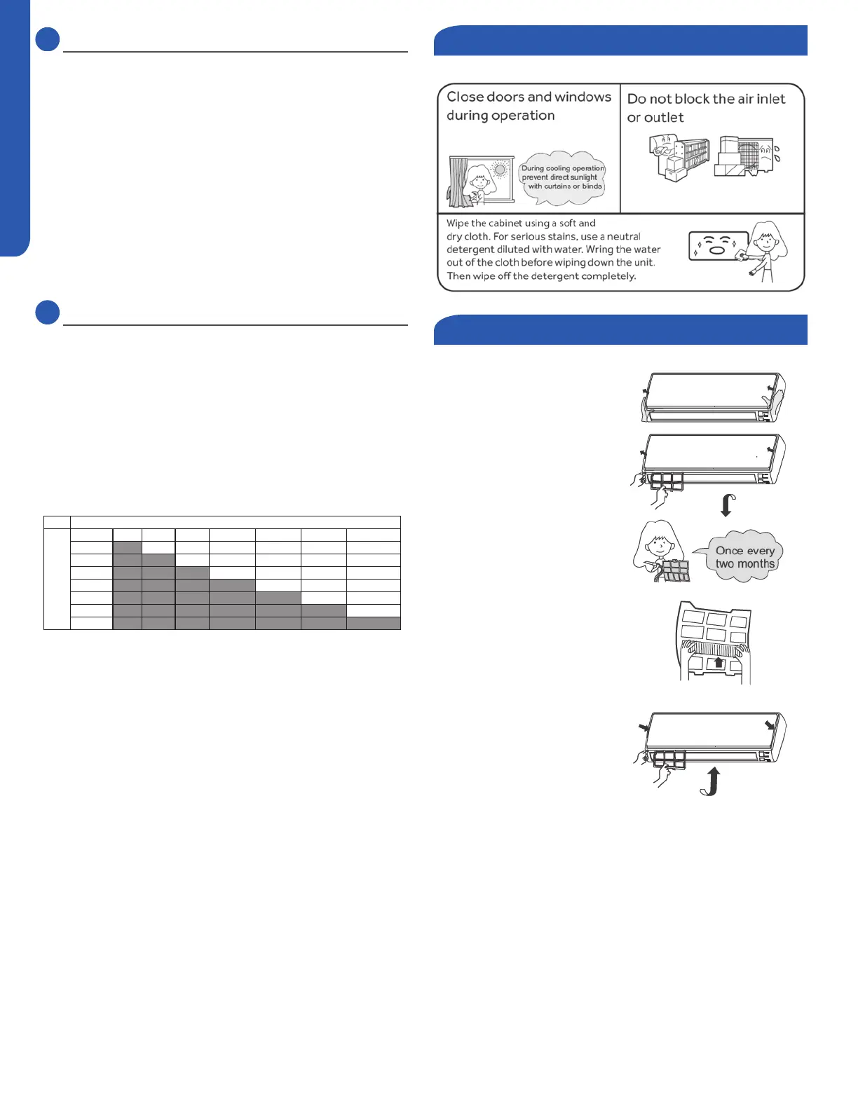
Optimizing Performance
Cleaning the Front Cover
1. Open the front cover by
pulling it upward
2. Remove the Filter: Gently
push up on the lter’s center
tab until it is released from
the stopper, and remove the
lter in a downward motion.
3. Clean the lter Use a
vacuum cleaner to remove
dust, or wash the lter with
water. After washing, dry the
lter completely.
4. Attach the lter Attach
the lter so that the
“FRONT” label is facing
outward. Make sure that
the lter is securly attached
behind the holding tabs. If
the lter is not attached
correctly the unit may not
achieve maximum eciency.
5. Close the front cover.
 Loading...