Harman® • P-Series Installation Manual_R18 • 2014 - ___ • 06/1811 3-90-436168i
4
Termination Location and Vent Information
A. Vent Termination Minimum Clearances
Figure 4.1
Figure 4.2
INSTALL VENT AT CLEARANCES SPECIFIED BY THE
VENT MANUFACTURER
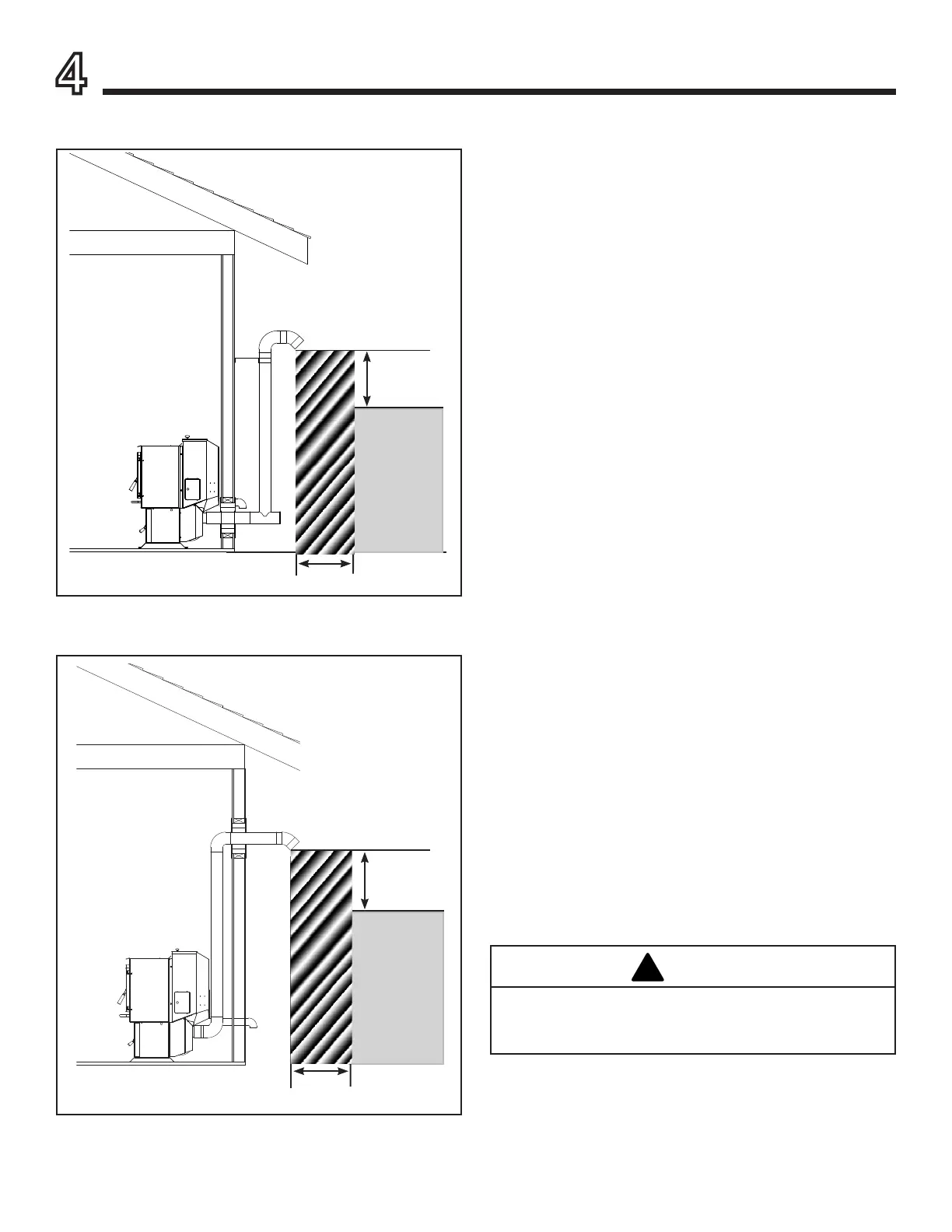
#1 Preferred method (Figure 4.1)
This method provides excellent venting for normal operation
and allows the stove to be installed closest to the wall. Two
inches from the wall is safe; however, four inches allows
better access to remove the rear panel. The vertical portion of
theventshouldbethreetovefeethigh.Thisverticalsection
will help provide natural draft in the event of a power failure.
Seal pipe joints with silicone or aluminum tape in addition to
the sealing system used by the manufacturer.
Do not place joints within wall pass-through.
#2 Preferred method (Figure 4.2)
This method also provides excellent venting for normal
operation but requires the stove to be installed farther from
the wall. The vertical portion of the vent should be three to
vefeethighandatleast1”fromacombustiblewall.This
vertical section will provide natural draft in the event of a
power failure.
Seal pipe joints with silicone or aluminum tape in addition to
the sealing system used by the manufacturer.
If the stove is installed below grade be sure the vent
termination is at least 12" above grade. The outlet must also
be 1 foot from the house/building.
Do not place joints within wall pass-through.
CAUTION
Keep combustible materials (such as grass, leaves,
etc.) at least 3 feet away from the ue outlet on the
outside of the building.
3 Ft.
to
Combustibles
3 Ft.
to Combustibles
3 Ft.
to
Combustibles
3 Ft.
to Combustibles
 Loading...