Harman® • P-Series Installation Manual_R18 • 2014 - ___ • 06/1823 3-90-436168i
E. Room Sensor Installation
The room sensor is a small temperature sensor on the end of
a 60" wire. This sensor is installed much like a standard wall
thermostat. There is a remote room sensor port on the rear
of the unit for easy external connection. Use standard 18-2
thermostat wire to extend the sensor to the desired location
(50' maximum). The room sensor should be installed in the
location where you want to control the temperature.
NOTE: Distances of more than 25 feet from the unit or in
another room are not recommended. The room sensor is
essentialfortheP-Seriesexcellentefciency.
NOTE: It is recommended that the room sensor be installed,
even if only installed on the rear of the unit as a return air
sensor.
F. Low Draft Voltage Adjustment
These units are pre-tested at the factory with exactly 120
VAC, 60 Hz. They are checked and adjusted for rebox
tightness, gasket leakage, motor operation and igniter
operation. The P-Series is then factory set at a mid-point
adjustment and in most cases will not need any adjustments.
NOTE: The factory low draft setting may not be correct
for the unit's permanent installation conditions.
The control board on the P-Series is equipped with a low
draft adjustment port located on the control face just to the
right of the igniter light. Figure 5.4. This voltage adjustment
is provided to allow the unit to be adjusted for the household
voltage where the unit is going to be in permanent operation.
NOTE: The line voltage varies from area to area and often
home to home.
The low draft voltage should be adjusted to achieve the most
efcient burn on low burn or "maintenance". This voltage
adjustment allows the installer to change the low voltage set
point approximately 10 volts. This adjustment should be done
by the installer during set up because a draft meter reading
is required to insure proper set up.
Combustion Motor
Speed Control
Low draft only set point.
The small straight
screwdriver slot is plastic;
therefore, the unit can
be adjusted while in
operation.
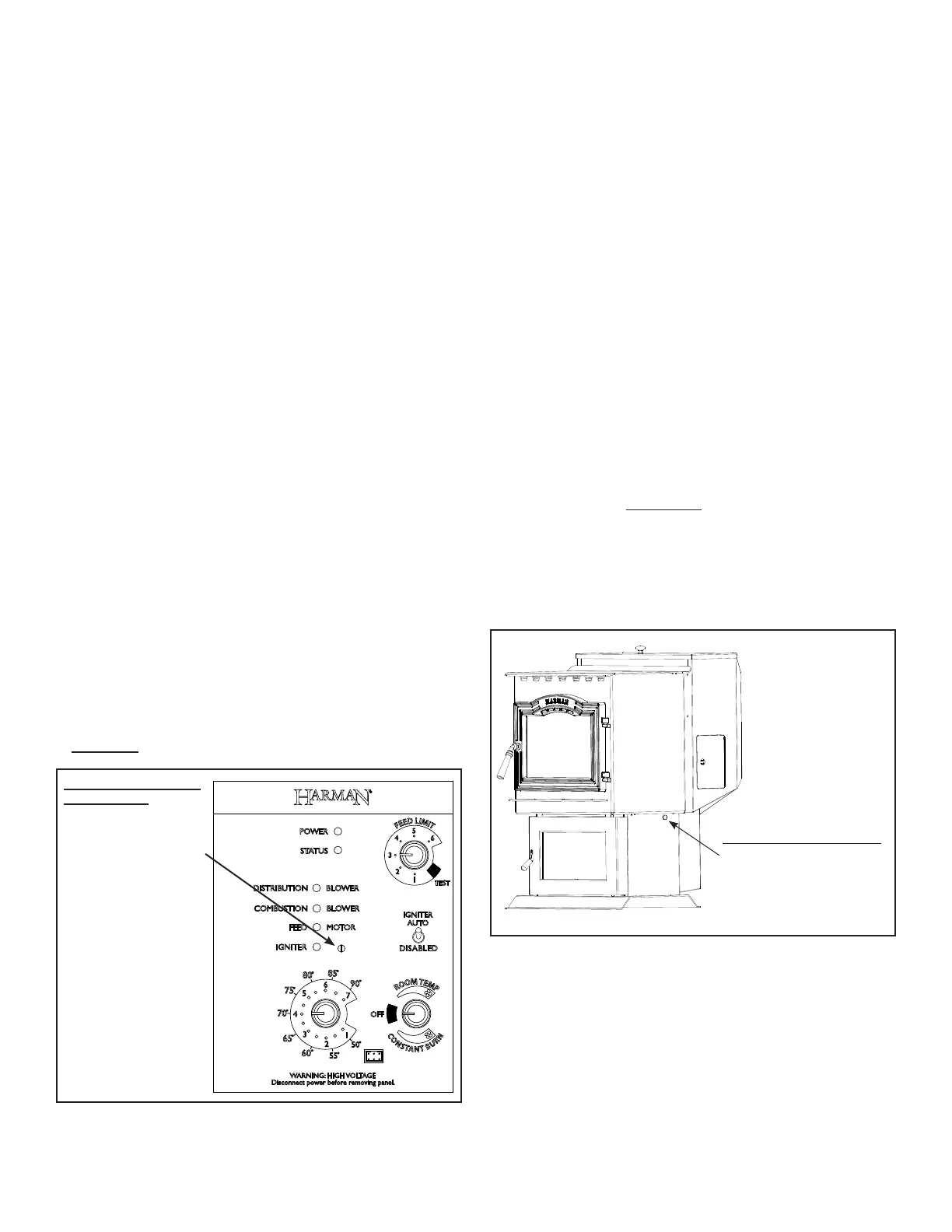
Draft Meter bolt hole location
On a P-Series the draft test hole is
undertheleftrearcorneroftherebox
on the pedestal base.
If the unit is not adjusted properly, it does not cause a safety
concern.Iftheunitisadjustedtoohigh,onlyefciencyislost.
If the unit is adjusted too low, the low draft pressure switch
will not allow the feed motor or the igniter to operate.
A simple draft test should be performed after completing the
uepipeinstallation.Torecordtheresultsforfuturereference:
1. Plug unit into a 120 VAC, 60 HZ outlet.
2. Close the hopper lid, front view door, and the ash pan
door.Neitherpelletsorarearerequiredforthistest.
3. Withthemodeselectorinthe“OFF”position,turnthefeed
adjuster to “TEST”.
4. Record the high draft_____in W.C. (Normal is -.50 to
-.60) The control will be on the High Draft for a total of 2
minutes.
5. After 1 minute, the combustion motor will go down to low
draft and the distribution blower will go on high. Allow
approximately 15 seconds to pass for the combustion
motor to slow before checking the low draft.
6. If the low draft is between -.35 and -.45, record the reading
_____ in W.C. If the reading is higher, slowly turn the
set screw counter-clockwise until the draft lowers. If the
reading is lower, very slowly turn the set screw clockwise
until the draft increases.
NOTE: In some cases, the draft may not go as low as
-.35 to -.45 even with the set screw completely counter-
clockwise. Ideally, you should just set it as low as
possible.
Figure 5.4
Figure 5.5
Connect the power cord to a 120 VAC, 60 Hz grounded
receptacle. (A surge protector is recommended to protect
the circuit board.) Also be sure that the polarity of the outlet
that the stove is plugged into is correct.
 Loading...