Page 8
USE ONLY HAYWARD GENUINE REPLACEMENT PARTS
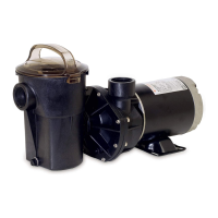
TriStar Variable Speed Pump
USE ONLY HAYWARD GENUINE REPLACEMENT PARTS
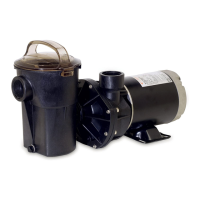
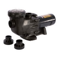
Hayward Variable Speed Pump
Page 2
Configuration Menu (Continued)
Establishing Connection with a Hayward Control System (e.g OmniLogic)
The last few screens in the Configuration Menu allow the user to alternate between “Stand Alone” Mode and RS485
Control Mode. RS485 Control Mode allows the pump to be controlled by a Hayward Control System when connected.
Firstly ensure the pump has been correctly wired to the Hayward control system. The pump must then be in RS485
Control Mode and connected to a GPO. The screens below are what will be shown whilst the pump establishes a
connection and begins communicating with the Hayward control system.
n
8
5
5 y4 8
This is the display for RS485 Control Mode selection.
The current display shows that RS485 Control Mode is NOT
selected and is in “Stand Alone” Mode. To leave the pump in
“Stand Alone” Mode press DISP/FUNC to exit the Configuration
Menu. Press either of the or arrow buttons to change modes.
▲ ▼
This screen shows that RS485 Control Mode has now been selected.
To save this selection, press the DISP/FUNC button.
The pump will now enter RS485 Control Mode.
When in configuration mode, the LED for the speed being configured will be constantly “FLASHING”.
When exiting configuration mode all three of the speed LED’s will “FLASH” to signify that all settings have been saved.
If the configuration mode has not been completely exited, after 2 minutes of inactivity the controller will save all of the
settings excluding the current screen settings and exit configuration mode.
Use the and arrow buttons to quickly adjust the current speed that the pump is running at. When a quick speed
change is performed the LED for the changed speed will be “FLASHING”. The LED will continue to flash until the speed
is saved, or until the timer runs out for that speed or the power is cycled to the pump.
The new speed is only saved by pressing simultaneously the and arrow buttons and then the LED for that speed
will illuminate solid.
▲
▲
▼
▼
Please Note: For full OmniLogic and RS485 connection instrustions please refer to the Communication Cable Manual
30-LITNSB019
8 5
This screen is shown
when the pump is
powering up
This second screen shows
for 3 seconds. This is the
current software revison.
The display will alternate between these two screens
if no, or until a connection with the
Hayward control system can be made.
0
1
0 0
Quick Speed Change
Saving Configuration Settings
This screen shows that a
connection has been
made with the system
but no speed input is
being sent. This will
continue until a speed
has been sent to the
pump.
Once a speed has been
sent from the OmniLogic,
the power output will be
displayed as the pump
speeds up. The screen
will alternate between
speed and power every 4
seconds.
s 4
I
l
USE ONLY HAYWARD GENUINE REPLACEMENT PARTS
Hayward Variable Speed Pump
0 0
4
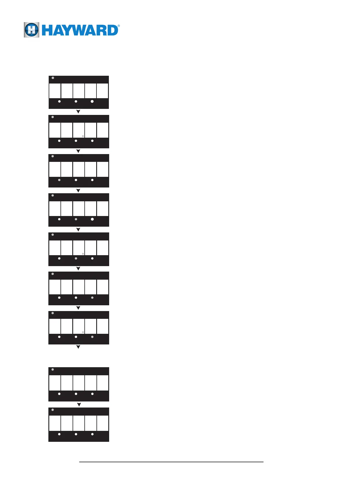
The first Configuration Menu screen is used to adjust the
duration of the priming time. Press or hold down either
or arrow button to adjust the run time between zero and
4 minutes. A setting of zero disables the priming cycle. Press
DISP/FUNC button to advance to next screen.
▲
▼
This screen allows the speed of V1 to be adjusted between
600 rpm and 3000 rpm by pressing or holding down either
or arrow button. Press DISP/FUNC button to advance
to the next screen.
▲
▼
This screen allows the speed of V2 to be adjusted between
600 rpm and 3000 rpm by pressing or holding down either
or arrow button. Press DISP/FUNC button to advance
to the next screen.
▲
▼
This screen allows the timer of V2 to be adjusted between
5 minutes and 18 hours by pressing or holding down either
or arrow button. Press DISP/FUNC button to advance
to the next screen.
▲
▼
This screen allows the speed of V3 to be adjusted between
600 rpm and 3000 rpm by pressing or holding down either
or arrow button. Press DISP/FUNC button to advance
to the next screen.
▲
▼
This screen allows the timer of V3 to be adjusted between
5 minutes and 18 hours by pressing or holding down either
or arrow button. Press DISP/FUNC button to advance
to the next screen.
▲
▼
Press and hold the DISP/FUNC button for several seconds
until the ConFg screen appears.
To ensure that the pump speeds and timers are setup according to the site specific individual requirements,
access the Configuration Menu as shown below:
 Loading...