USE ONLY HAYWARD GENUINE REPLACEMENT PARTS
Page 14 of 20 Max-Flo XL Pump IS2300 Rev-A1
7.5. Replacing the Impeller and Diffuser
11. Screw the impeller (item#10) onto the motor shaft in a clockwise direction. Tighten snugly by holding motor
shaft with wrench as noted in step #4.
12. Place the diffuser (item #9) over the impeller (item#10) onto the seal plate (item#13), aligning the three (3)
protruding pins with the matching holes in the seal plate (item#13). Note: Flat side of diffuser rim (item #9) will
face up. Replace three (3) diffuser screws (item #7), Torque screws to 20 in-lbs.
7.6. Replacing the Motor Assembly
13. Re-attach motor end cover/canopy by using the two (2) hex shaped screws. Slide the motor assembly with the
diffuser (item#9) in place, into pump/strainer housing (item#4), being careful not to disturb the diffuser o-ring
(item#8).
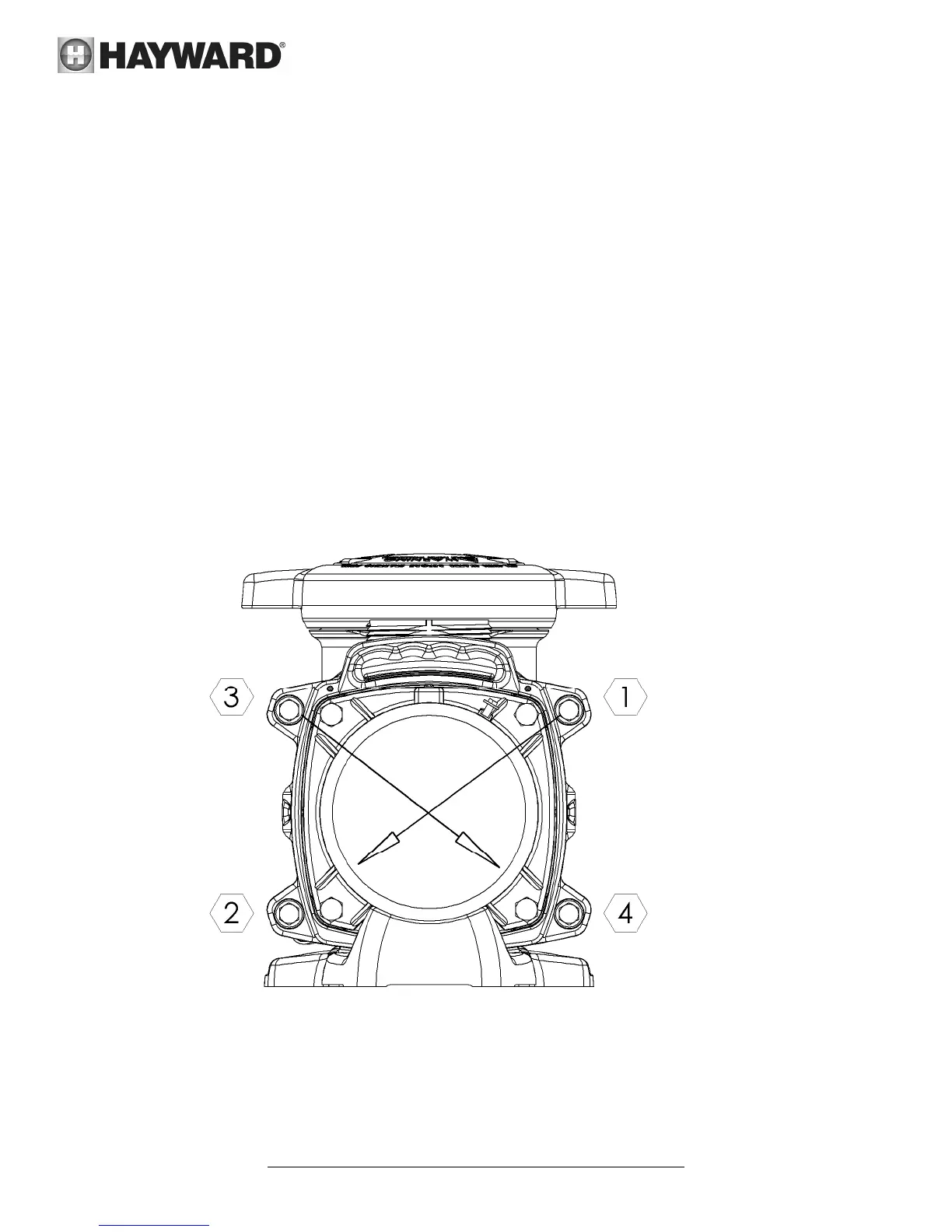
14. Re-attach assembly to pump/strainer housing (item#4) using the four (4) 5/16”" x 1 3/4" hex head bolts. (Be
sure housing o-ring (item#11) is in place, and lubricated. Replace if damaged). Tighten alternately and evenly to
185 in-lbs using torque pattern in the following diagram.
HOUSING BOLT TORQUE PATTERN
 Loading...