Curve Series
6 Heat&Glo•7076-108 2/11/2014
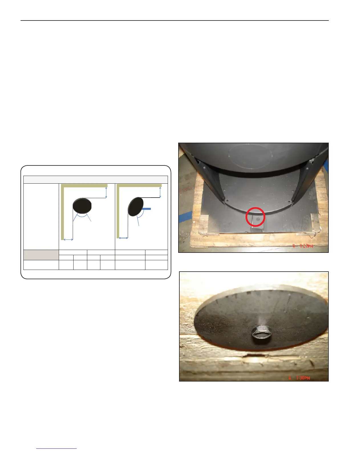
I. Removal of Curve from Pallet
1. Remove the two 11 mm bolts holding the brackets in the
front and rear of the base on the unit, this requires holding
the bolt on the bottom side of the pallet as shown in picture
below on right
2. Tilt unit back unit the front bracket is able to tilt forward
and be removed from bottom of unit, repeat tilting forward
and removing rear bracket. (the brackets need to swing
down and slightly back in order to be pulled from unit)
3.Unitcannowbemovedoffpallet.
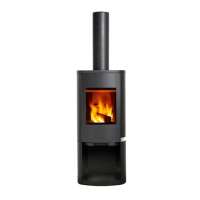
SINTEF evaluation of safety distances
Curve 300 with internal
shield installed
Combustible wall Combustible wall Brick wallBrick wall
x [mm] x [mm]y [mm] y [mm] z [mm]z [mm]
400 100 200 50 300 100
y
x
z
z
D. Leveling the Unit
Fourlevelingboltshavecomeinstalledontheunit.Follow-
ing installation, adjustments can be made to the heights of
the four bolts from the top of the base pan. Use a hex head
bit to adjust the height of each of the four legs. When in its
nalstate,theunitshouldbesecureandnotrock.
E. Position Near to Non-ammable Walls
Whenpositioningnearanon-ammablewall,werecom-
mend you keep a minimum distance of 50 mm between the
rear of the product and the wall for cleaning purposes.
F. Distance to Furniture: 1000 mm
But please check to avoid furniture or other furnishings
being dried out due to being too close to the stove.
G. Distance to Flammable Walls
Curve100and300
H. Component Pack
The component pack contains the following:
•Manual
•Gloves
•Outsideairconnectingplate
•Topadapterring
•Topuecoverplate
•Outsideairscreen
Fig. 6.2
Fig. 6.3
Fig. 6.1
 Loading...