User Manual of DS-7200/7300/8100-SH Series DVR
22
Table 1.7 Description of Rear Panel
BNC connector for analog video input.
BNC connector for video output.
Connects USB mouse or USB flash memory devices.
DB15 connector for VGA output. Display local video output and menu.
RCA connector for audio input.
RCA connector for audio output.
RJ45 10M/100M Ethernet interface.
Connector for RS-485 devices. Connect the D+ and D- terminals to T+
and T- of PTZ receiver respectively.
Switch for turning on/off the device.
Ground (needs to be connected when DVR starts up).
DS-7224/7232HVI-SH and DS-7224/7232HWI-SH:
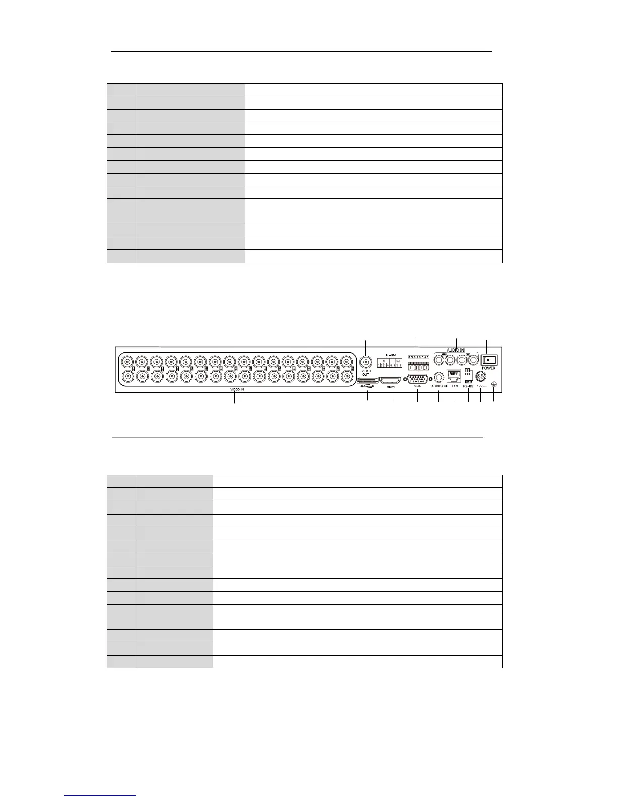
The rear panel of DS-7232HVI-SH/DS-7232HWI-SH is shown in Figure 1.9.
Figure 1.9 Rear Panel of DS-7232HVI-SH and DS-7232HWI-SH
Note: The rear panel of DS-7224HVI-SH/DS-7224HWI-SH provides 24 video input interfaces.
Table 1.8 Description of Rear Panel
BNC connector for analog video input.
BNC connector for video output.
Connects USB mouse or USB flash memory devices.
DB15 connector for VGA output. Display local video output and menu.
RCA connector for audio input.
RCA connector for audio output.
Connector for alarm input/output.
RJ45 10M / 100M / 1000M Ethernet interface.
Connector for RS-485 devices. Connect the D+ and D- terminals to R+ and R-
terminals of PTZ receiver respectively.
Switch for turning on/off the device.
Ground(needs to be connected when DVR starts up)
DS-7316HFI-SH and DS-7316HWI-SH:
The rear panel of DS-7316HFI-SH and DS-7316HWI-SH DVR is shown in Figure 1.10.
 Loading...