User Manual of DS-7200/7300/8100-SH Series DVR
24
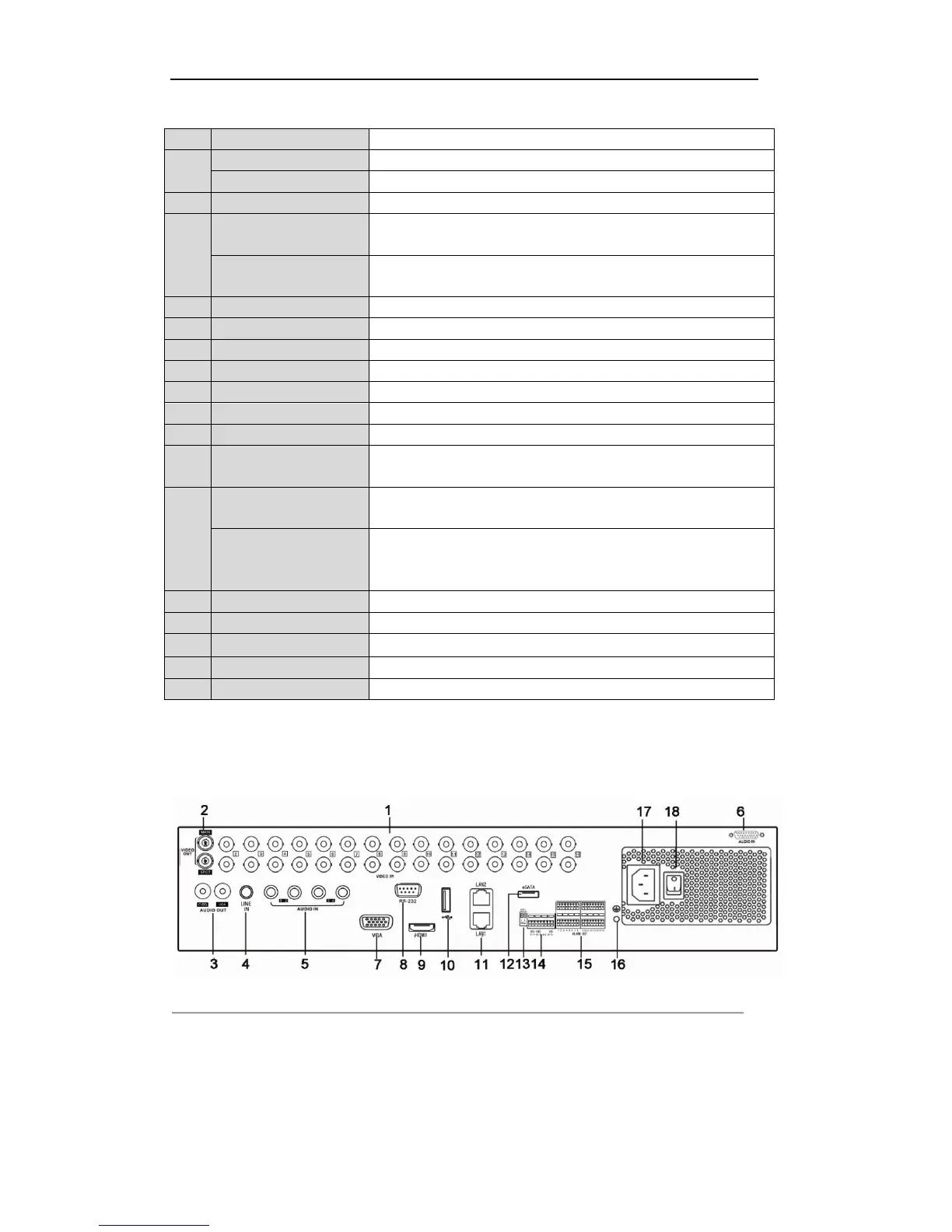
Table 1.10 Description of Rear Panel
BNC connector for video output.
BNC connector for spot video output.
BNC connector for analog video input.
RCA connector for audio output. This connector is synchronized with
CVBS video output.
RCA connector for audio output. This connector is synchronized with
VGA video output.
RCA connector for two-way audio input.
RCA connector for audio input.
DB15 connector for VGA output. Display local video output and menu.
Connects USB mouse or USB flash memory devices.
RJ45 10M/100M/1000M Ethernet interface.
Connector for RS-232 devices.
RS-485 termination switch. Up position is not terminated.
Down is terminated with 120Ω resistance.
Connector for RS-485 devices. Connect the T+ and T- terminals to the
R+ and R- terminals of PTZ receiver respectively.
Connect the D+ and D- terminals to Ta and Tb terminals of the controller.
For cascading devices, the first DVR’s D+ and D- terminals should be
connected with the D+ and D- terminals of the next DVR.
Connector for alarm input/output.
Connects external SATA HDD, DVD-R/W.
Ground(needs to be connected when DVR starts up)
Switch for turning on/off the device.
DS-8100-SH:
The rear panel of DS-8100-SH DVR is shown in Figure 1.12.
Figure 1.12 Rear Panel of DS-8132HCI-SH, DS-8132HFSI-SH and DS-8132HWSI-SH
Note: DS-8124HCI-SH, DS-8124HFSI-SH and DS-8124HWSI-SH models provide 24 video input interfaces
on the rear panel.
 Loading...