Network Traffic Camera • User Manual
72
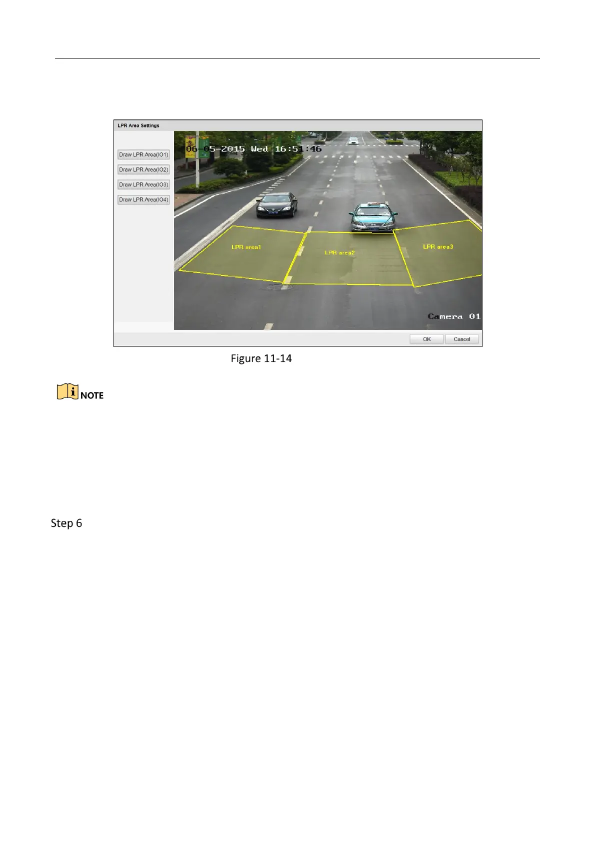
3) Click on the live view window to point out a corner of the LRP area, and right click the
mouse to finish drawing.
Draw LPR Area
Polygon with 3 to 20 sides is supported.
Click Draw LPR Area (IO x) again to delete the previous drawn area and re-draw the LRP
area.
4) Click OK to save the areas and exit the LPR area settings page.
5) (Optional) Check Display All Areas to display all the LPR areas, or only the LPR area of
the external input that is under configuration will be displayed.
Select the external input tab to configure its parameters.
1) (Optional) If the lane is emergency lane, check Occupy Emergency Lane Capture, and
when there is vehicle passing on emergency lane, capture will be triggered.
2) Set the linkage lane by entering Lane No., and it should be the lane No. connected to
the external induction coils.
3) Select Lane Type. You can select Normal Lane and Highway Emergency Lane
according to actual lane.
4) Select Level Status. You can select Low-going Edge, Rising Edge, and Rising Edge and
Low-going Edge as requested.
5) Select Capture Pictures. Up to 5 can be selected. 0 refers to capture no picture.
6) Select Capture Interval type as Time, and set the interval time.
7) Select the linkage flashlight output.
 Loading...