42
Installation RS20/22/30/32/40
Release
05
12/2015
1.4 Display elements
After the supply voltage is set up, the software starts and initializes itself.
Afterwards, the device performs a self-test. During this process, various
LEDs light up. The process takes around 60 seconds.
Device state
These LEDs provide information about conditions which affect the
operation of the whole device.
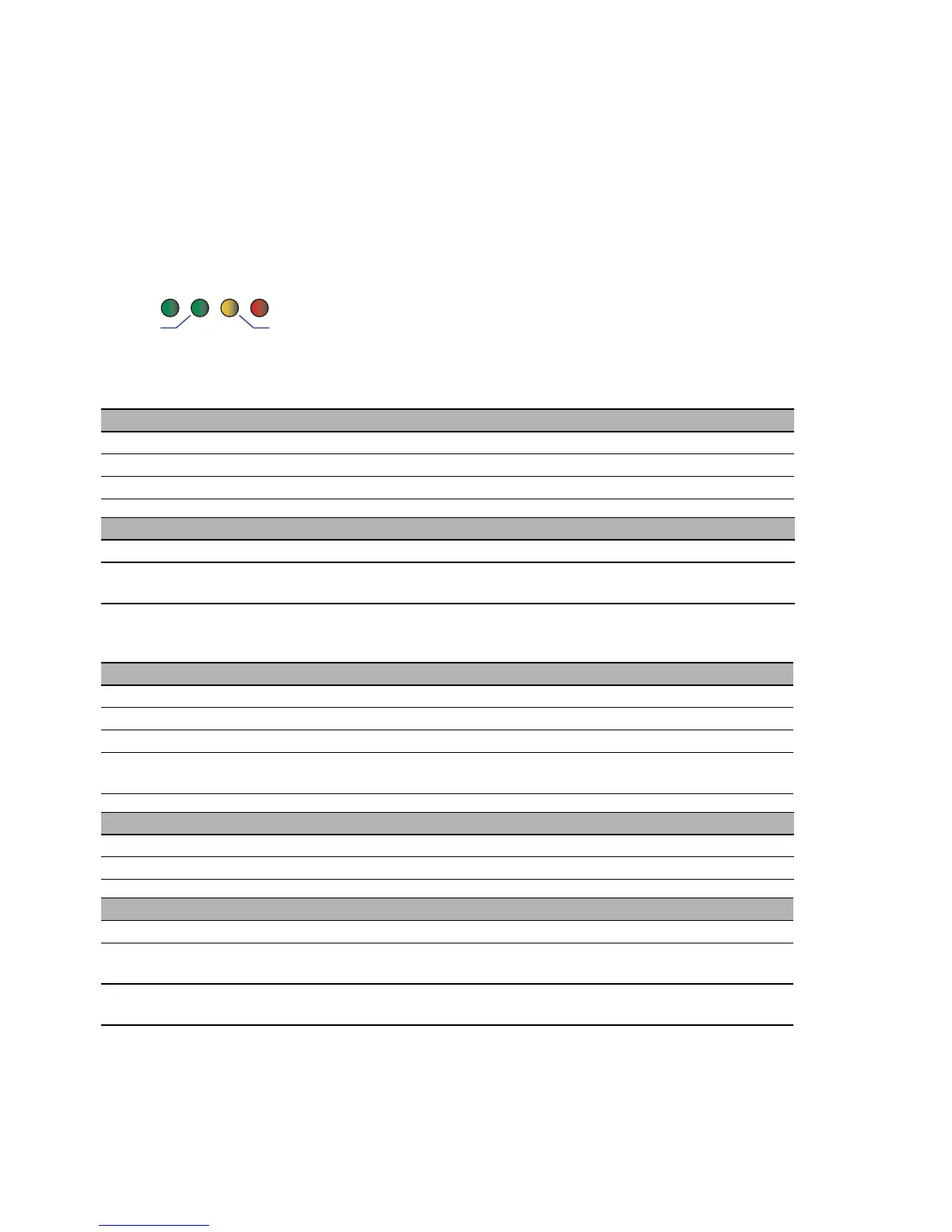
Figure 13: Device status LEDs
P - Power (green/yellow LED)
Glowing green Both supply voltages are on
Glowing yellow There is only one supply voltage (P1 or P2) on
Not glowing Supply voltages P1 and P2 are too low
FAULT - detected error, signal contact (red LED)
a
a. If the manual adjustment is active on the “FAULT” signal contact, then the detected error
display is independent of the setting of the signal contact.
Glowing red The signal contact is open, i.e. it is reporting a detected error.
Not glowing The signal contact is closed, i.e. it is not reporting
a detected error.
RM - Ring Manager (green/yellow LED)
Glowing green RM function active, redundant port disabled
Glowing yellow RM function active, redundant port enabled
Not glowing RM function not active
Flashing green Incorrect configuration of the HIPER-Ring (e.g. the ring is not
connected to the ring port).
Stand-by
Glowing green Stand-by mode enabled
Not glowing Stand-by mode not enabled
RM and Stand-by - display saving processes of the AutoConfiguration Adapter (ACA)
Flashing alternately Error during saving process.
LEDs flash synchronously, two
times a second
Loading configuration from the ACA.
LEDs flash synchronously,
once a second
Saving the configuration in the ACA.
 Loading...