EasyManua.ls Logo

Hirschmann RS20 series User Manual

Hirschmann RS20 series
80 pages
To Next Page IconTo Next Page
To Previous Page IconTo Previous Page
Page #64 background image
64
Installation RS20/22/30/32/40
Release
05
12/2015
7 Technical data
General technical data
Dimensions
B × H × T
RS20-0400...
RS20-08..., RS20-09..., RS30-0802
RS20-16..., RS20-17..., RS30-1602
RS20-24..., RS20-25..., RS30-2402
RS40-0009CCCCS...
RS40-0009CCCCE...,
RS40-0009CCCCT...
1.85 in. × 5.16 in. × 4.37 in.
(47 mm × 131 mm × 111 mm)
2.91 in. × 5.16 in. × 4.37 in.
(74 mm × 131 mm × 111 mm)
4.33 in. × 5.16 in. × 4.37 in.
(110 mm × 131 mm × 111 mm)
4.33 in. × 5.16 in. × 4.37 in.
(110 mm × 131 mm × 111 mm)
2.91 in. × 5.16 in. × 4.37 in.
(74 mm × 131 mm × 111 mm)
4.33 in. × 5.16 in. × 4.37 in.
(110 mm × 131 mm × 111 mm)
RS22-08..., RS22-09..., RS32-0802
RS22-16..., RS22-17..., RS32-1602
RS22-24..., RS22-25..., RS32-2402
3.54 in. × 5.39 in. × 4.53 in.
(90 mm × 137 mm × 115 mm)
4.72 in. × 5.39 in. × 4.53 in.
(120 mm × 137 mm × 115 mm)
4.72 in. × 5.39 in. × 4.53 in.
(120 mm × 137 mm × 115 mm)
PoE power supply unit RPS
90/48V LV
PoE power supply unit RPS
90/48V HV
2.36 in. × 5.39 in. × 4.53 in.
(60 mm × 137 mm × 115 mm)
2.36 in. × 5.39 in. × 4.53 in.
(60 mm × 137 mm × 115 mm)
Weight RS20-0400...
RS20-08..., RS20-09..., RS30-0802
RS20-16..., RS20-17..., RS30-1602
RS20-24..., RS20-25..., RS30-2402
RS40-0009CCCCS...
RS40-0009CCCCE...,
RS40-0009CCCCT...
14.11 oz (400 g)
14.46 oz (410 g)
21.16 oz (600 g)
20.90 oz (650 g)
18.70 oz (530 g)
21.16 oz (600 g)
RS22-08..., RS22-09..., RS32-0802
RS22-16..., RS22-17..., RS32-1602
RS22-24..., RS22-25..., RS32-2402
28.92 oz (820 g)
40.57 oz (1150 g)
42.33 oz (1200 g)
PoE power supply unit RPS
90/48V LV
PoE power supply unit RPS
90/48V HV
27.16 oz (770 g)
26.10 oz (740 g)
Power supply
RS20-..., RS30-...,
RS40-...
Nominal voltage AC 24 V
Max. voltage range AC 18 V ... 30 V
(incl. max. tolerances)
Rated voltage range DC 12 V ... 48 V
Max. voltage range DC 9.6 V ... 60 V (incl. max. tolerances)
Connection type 6-pin terminal block with snap lock
Power loss buffer > 10 ms
Back-up fuse Nominal rating:
Characteristic:
3.5 A
slow blow
Peak inrush current < 14 A
Question and Answer IconNeed help?

Do you have a question about the Hirschmann RS20 series and is the answer not in the manual?

Hirschmann RS20 series Specifications

General IconGeneral
Port CountUp to 24 ports
MountingDIN Rail
Operating Temperature-40°C to +70°C
Protection ClassIP30
Switching TechnologyStore-and-forward
Port Type and Speed10/100BASE-TX, 100BASE-FX
Power Supply24 V DC or 110-230 V AC
CertificationsCE, UL, cUL, DNV, GL, ABS, IECEx, ATEX
ManagementWeb, SNMP, CLI
RedundancyMRP, RSTP
DimensionsVaries depending on model
Weight500 g

Summary

Safety Instructions

General Safety Instructions

Covers general safety, certified usage, and installation site requirements.

Device Safety and Grounding

Supply Voltage Safety

PoE Power Supply Safety

ATEX Directive Safety

Explosion Hazard Area Safety

IECEx Certification Safety

E Marking

CE Marking

Component and Compliance Notes

About this Manual

Manual Key and Overview

Explains symbols and lists available manuals.

1 Description

Device Variants Description

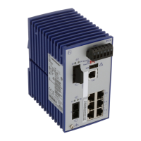
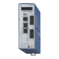
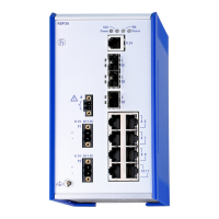
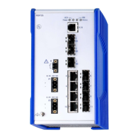
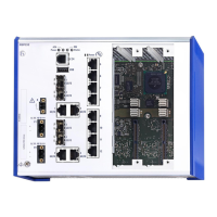
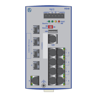
Details product variants, number of ports, and media types.

PoE Device Variants

Describes device variants that support Power over Ethernet.

Ethernet Ports Overview

Details types and specifications of Ethernet ports.

Display Elements

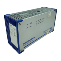
Explains the function of device status LEDs.

Management Interfaces

Describes USB and V.24 interfaces for management.

2 Installation

Package Contents Check

Procedure to verify all items are included and undamaged.

Device Installation and Grounding

Instructions for installing and grounding the device safely.

SFP Transceiver Installation

Steps for optional installation of SFP transceivers.

DIP Switch Settings Adjustment

How to configure DIP switch settings for device options.

Terminal Block Connections

How to connect the terminal block for power and signal.

Terminal Block Mounting

Procedure for mounting the terminal block onto the device.

Ferrite Connection

Instructions for connecting the ferrite for EMC compliance.

Device Operation Start

Steps to begin operating the device after installation.

Data Cable Connection

Recommendations for connecting data cables.

Inscription Label Filling

Guidance on filling out the device inscription label.

3 Making Basic Settings

4 Monitoring Ambient Air Temperature

5 Maintenance and Service

6 Disassembly

Removing the Device

Step-by-step instructions for safely removing the device.

Removing SFP Transceiver

7 Technical Data

EMC and Immunity Compliance

Network Range Specifications

Accessories and Order Information

A Further Support

Related product manuals