Installation RSPL 20/30
Release
04
02/2013
25
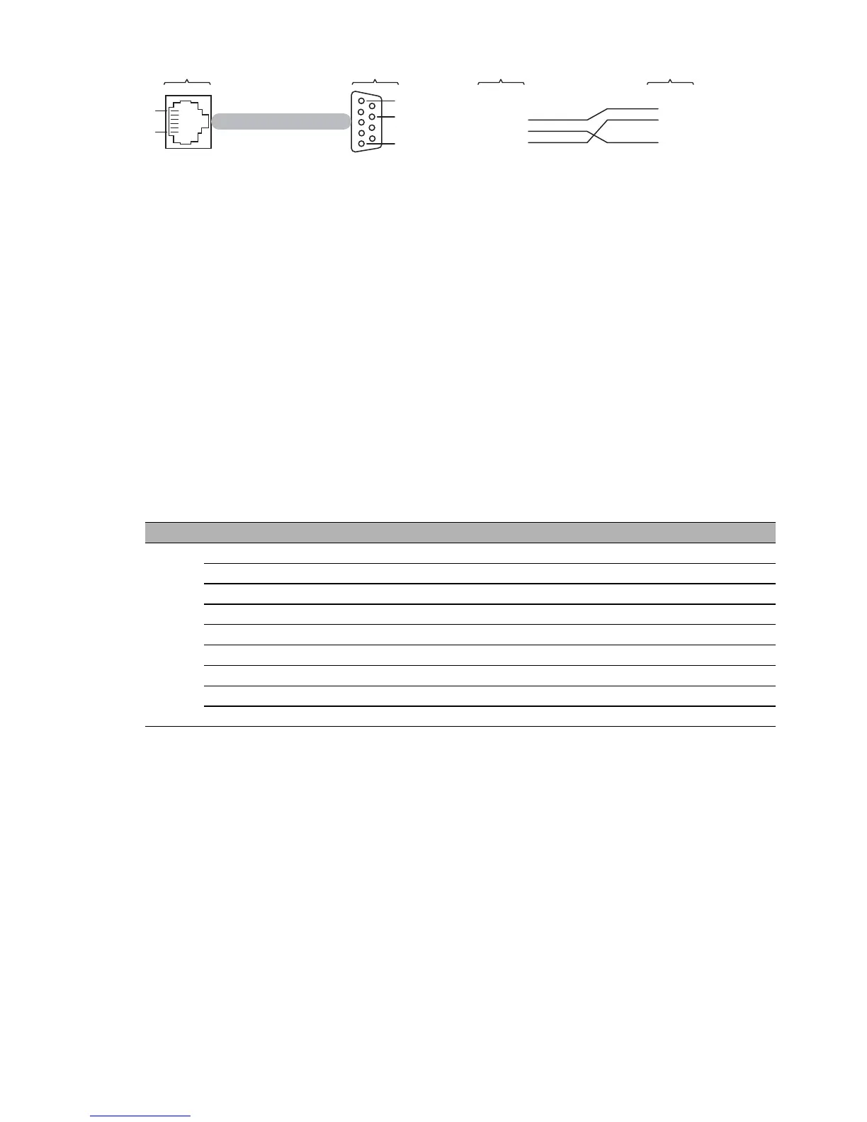
Figure 2: Pin assignment of the V.24 interface and the DB9 connector
Note: You will find the order number for the terminal cable, which is supplied
separately, in the Technical Data chapter (see page 49).
1.8.2 SD card interface
Note: The location on the device is described on page 20 “Rear view”.
On the front of the device there is an LED display that informs you about the
status of the interface.
The SD card interface allows you to connect the AutoConfiguration Adapter
ACA31 storage medium. This is used for saving/loading the configuration
data and diagnostic information, and for loading the software.
See “Accessories” on page 49.
Mode Pin No. Description Type
a
a. S - voltage supply
I - input
O - output, uses push-pull driver
PP - I/O, uses push-pull driver
Description
SD 1 CD/DAT3 I/O/PP Card detection / data line (bit 3)
2 CMD PP Command / reply
3 VSS1 S Supply voltage (ground)
4 VDD S Supply voltage
5 CLK I Clock input
6 VSS2 S Supply voltage (ground)
7 DAT0 I/O/PP Data line (bit 0)
8 DAT1 I/O/PP Data line (bit 1)
9 DAT2 I/O/PP Data line (bit 2)
Table 7: Pin connection of SD card
1
1
8
5
6
2
3
5
1
2
3
4
5
6
CTS
n.c.
TX
GND
RX
RTS
RJ11
DB9
RJ11
DB9

 Loading...