12
DP45
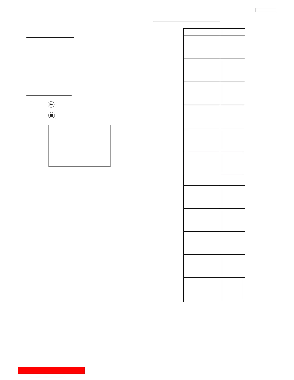
Parameter Normal
ADJ. DISP 0F
DEMO WAIT
1F
INT. START 13
V. SQUEEZE 10
INT STEP 1 02
INT STEP 2 06
INT BAR 2D
INT DELAY 01
MGF STEP 1 50
MGF STEP 2 06
MGF BAR 1B
MGF DELAY 01
SEL. STAT. 00
LINE WID 7F
ADD LINE 09
SENSOR CK 00
PORT 0 07
PORT 1 06
PORT 2 05
PORT 3 04
PORT 4 03
PORT 5 02
PORT 6 01
PORT 7 00
AD LEVEL 03
CENT. BAL 01
E. DISPLAY 00
ADJ. TIMS 60
AD LEVEL 05
AD NOISE 0A
OVER. LF-H 01
OVER. LF-V 00
OVER. RI-H 00
OVER. RI-V 00
PHASE MOT 60
H. BLK-RV 0A
H. BLK-GV 03
H. BLK-BV 09
H. BLK-H 20
PON DELAY 0F
IR-CODE 00
INITIAL 50 9E
MGF 50 96
CENTER 50 FE
STAT 50 FE
DYNA 50 9F
2.11.1
MAGIC FOCUS Character Set-Up
This instruction should be applied when a new DCU
is being replaced.
Adjustment Preparation
(1) Receive NTSC RF or video signal.
(2) With Power off, PRESS and HOLD the SERVICE
ONLY button on DEF./CONV. PWB, then press the
Power On/Off, when picture appears release
SERVICE ONLY switch (Internal crosshatch is
displayed without conv. correction data).
(3) Set R/C to DCAM mode (refer to page 47).
(4)
Press the DAY/NIGHT button 2 times for ROM READ
operation. Picture will appear with convergence
correction data.
Adjustment Procedure
(1) Press key on R/C. (One additional line appears
near the top and near the bottom.)
(2) Press key, then ADJ. PARAMETER mode is
displayed as following.
(3) Press CURSOR PAD
F or E to change the ADJ.
DISP. data.
(4) Press CURSOR PAD H to access DCU parameter.
Change the data as shown on Table 1, DCU
Parameter.
(5) Press Aspect key 2 times to write changed data into
EEPROM. (First press ADJ. PARAMETER/ROM
WRITE? is displayed for alarm. 2nd press, writes
data into EEPROM. Green dots appear after
completion of operation.)
(6) Press MUTE/VOLUME key 3 times to exit from ADJ.
PARAMETER mode.
ADJ. PARAMETER
ADJ. DISP.: 0F
DEMO WAIT:1F
INT. START:13
V. SQUEEZE:10
TABLE 1. - DCU PARAMETER
BACK TO ADJUSTMENTS
 Loading...