13
DP45
(7) Press ASPECT key 2 times to write the changed
data in EEPROM. (First press, ROM WRITE ? 2nd
press, writes data into EEPROM. Green dots appear
after completion of operation.)
(8) Push POWER key (on control panel) to exit from
PATTERN mode.
Adjustment Procedure
(1) Receive NTSC RF or video signal.
(2) With Power off, PRESS and HOLD the SERVICE
ONLY button on DEF./CONV. PWB, then press the
Power On/Off, when picture appears release
SERVICE ONLY button (Internal crosshatch is
displayed without conv. correction data).
(3) Set R/C to DCAM mode (refer to page 47).
Adjustment Procedure
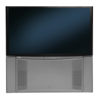
(1) Press key on R/C. (One addtional line appears
near the top and near the bottom.)
(2) Press C.C. key, then MAGIC FOCUS PATTERN
mode is displayed as follows:
(3) Use [6] key on remote control to rotate the arrow.
Arrow indicates each sensor position. (Upper left
corner, middle top, upper right corner, right middle, in
this order).
(4) Use the keys to switch color of pattern.
INFO : Green pattern
0 : Red pattern
INPUTS : Blue pattern
(5) Press CURSOR PAD
F or E to change the data
value to the horizontal direction. Press CURSOR
PAD G or H to change the data value to the vertical
direction.
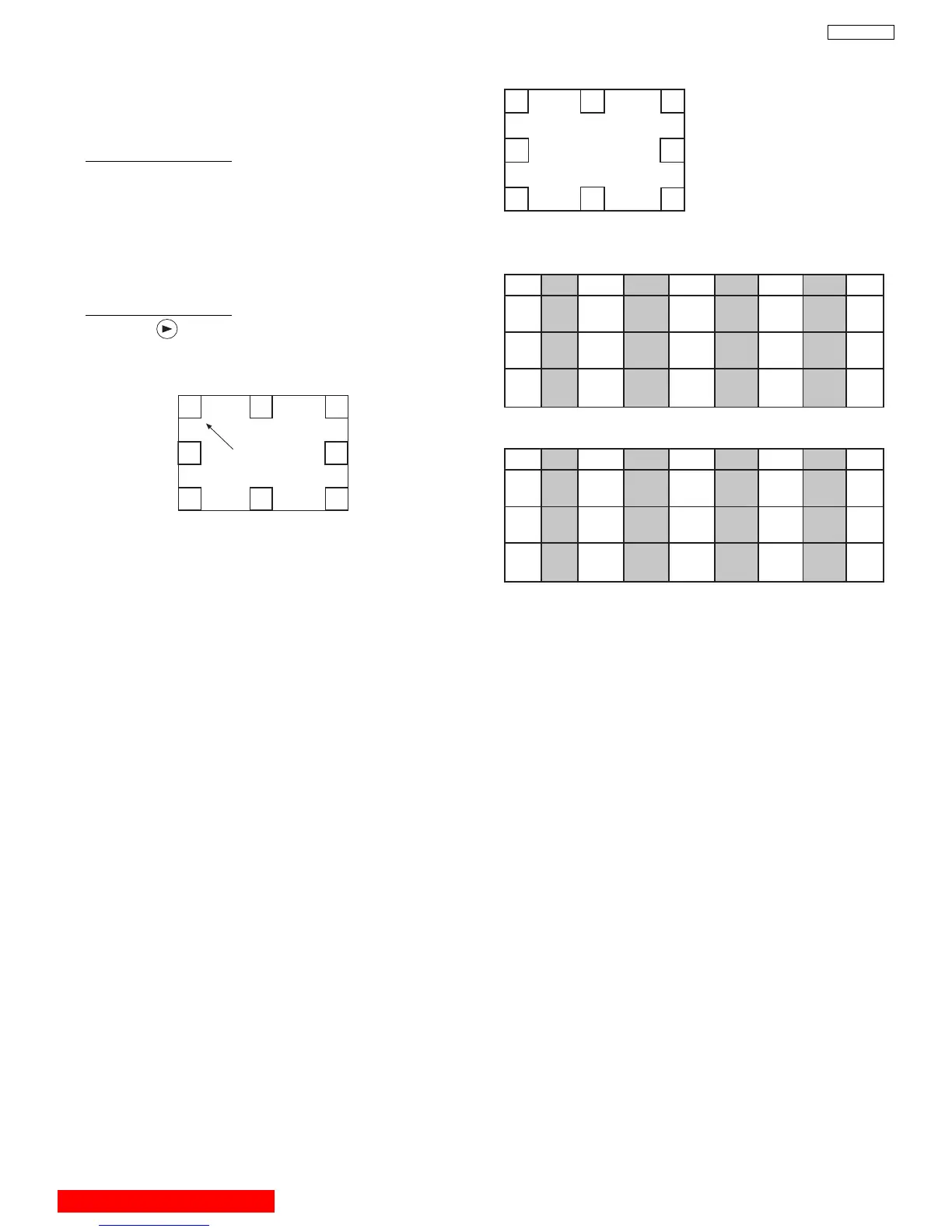
(6) Set the data as shown below:
1
3
5
7
0123 4567
RH 04 00 fc 02 fc 00 04 fe
RV ff fe 01 00 fe 01 00 00
GH 04 00 fc 02 fc 00 04 fe
GV ff fe ff 00 ff 01 00 00
BH 04 00 fc 02 fc 00 04 fe
BV ff fe ff 00 00 01 ff 00
Pattern Position
Normal Mode
0
2
4
6
Pattern: 51” & 57” (Sensor: 20mm)
0123 4567
RH 08 02 f6 fe f6 02 08 00
RV 04 02 06 00 fb ff fe 00
GH 08
03
00 f8 00 f8 00 08 00
GV 01 04 00 fc ff fe 00
BH 08 fe f8 fe f8 fe 08 00
BV 05 01 02 00 fd ff fc 00
Normal Mode
Pattern: 65”
2.11.2 MA
GIC FOCUS Pattern Set-Up
NOTE: (1) This instruction should be applied when a new
DCU is being replaced.
(2) This instruction shows how to set up the pattern
position for MAGIC FOCUS.
BACK TO ADJUSTMENTS
 Loading...