EasyManua.ls Logo

Hitachi E590 User Manual

Hitachi E590
36 pages
To Next Page IconTo Next Page
To Previous Page IconTo Previous Page
Page #15 background imageLoading...
Page #15 background image
Number Item Description
4 Uninterruptible
power supply port
NA
5 Cache flash
memory
NA
Number Item Description
1 BACKUP STS LED
Green: Restoration in progress following power
outage.
Fast Blink: Restoring.
Slow Blink: Restoring or sequential shutdown
in progress.
2 CTL ALM LED
Red: Controller can be removed.
Failure with the controller's power supply unit.
Amber: LAN reset switch was pressed.
3 ALARM LED (for CFM ) Red: Cache flash memory can be removed.
Front-end modules
The front-end modules (FEMs), also called channel boards (CHBs), control the transfer of
data between the host and cache memory. The storage system supports Fibre Channel (FC)
and iSCSI front-end modules (FEMs) for attachment to host servers. The front-end module
LEDs indicate the operating status of the module.
Front-end modules
Chapter 2: Hardware overview
Hitachi Virtual Storage Platform E590 and E790 Hardware Reference Guide 15

Other manuals for Hitachi E590

Question and Answer IconNeed help?

Do you have a question about the Hitachi E590 and is the answer not in the manual?

Hitachi E590 Specifications

General IconGeneral
CategoryStorage
ModelE590
RAID LevelsRAID 0, 1, 5, 6, 10
Power SupplyRedundant power supplies
Host ConnectivityFibre Channel, iSCSI
Cache MemoryUp to 256GB
Drive Types SupportedSSD, SAS HDD
Operating System SupportWindows Server, Linux, VMware
Dimensions (H x W x D)Varies by configuration
WeightVaries by configuration

Summary

Hitachi Virtual Storage Platform Introduction

Key Features of VSP E590 and E790

Overview of the storage system's high performance, reliability, and scalability.

Storage System Specifications Overview

Details the operational and performance specifications for the storage system.

Hitachi Virtual Storage Platform Hardware Overview

Controller Chassis Components and LEDs

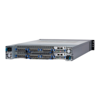
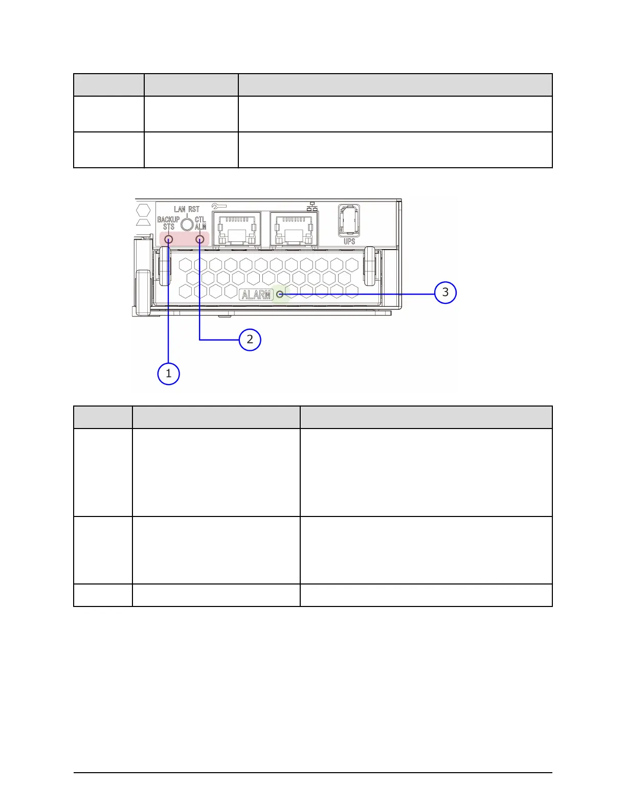
Describes the components and status LEDs of the controller chassis.

Hitachi Virtual Storage Platform Specifications

Environmental Operating Requirements

Provides temperature, humidity, vibration, and noise level requirements for operation.

Managing Hitachi Virtual Storage Platform Power

Procedure for Powering On the Storage System

Step-by-step instructions for powering on the storage system using the main switch.

Procedure for Powering Off the Storage System

Procedure for safely powering off the storage system and stopping power supply.

Related product manuals