See the following table for the pin assignments:
RJ 45 Pin Number Ethernet Signal Name
1 TX+ (Transmitted Data+)
2 TX- (Transmitted Data-)
3 RX+ (Received Data+)
4 N/C
5 N/C
6 RX - ( Received Data-)
7 N/C
8 N/C
Table 4-6: Ethernet Ports
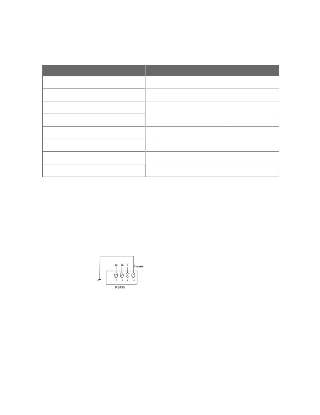
RS485 Ports
The CN100 controller has one RS485 port to some specific
equipment. Each port has five terminals: 485 A+, 485 B-, chassis
ground and termination. See the following picture for the RS485 pin
assignment.
Figure 4-7: Pin Assignment of RS485 Port
The regulations are recommended to follow:
n All chassis ground terminals of RS485 must be connected to the
earth.
n Use single shielded two wire twisted cable.
RS485 Terminals: A termination resistor (120-ohm) is used within
CN100 controller to match the characteristic impedance of the cable
32
Chapter 4 - CN100 Platform Installation

 Loading...