INSTALLATION (CONT)
With Searchpoint Optima
This procedure describes how the DVC100 (M) MK2 is installed at the
mounting location and then the Optima gas detector is tted to the
Termination Unit.
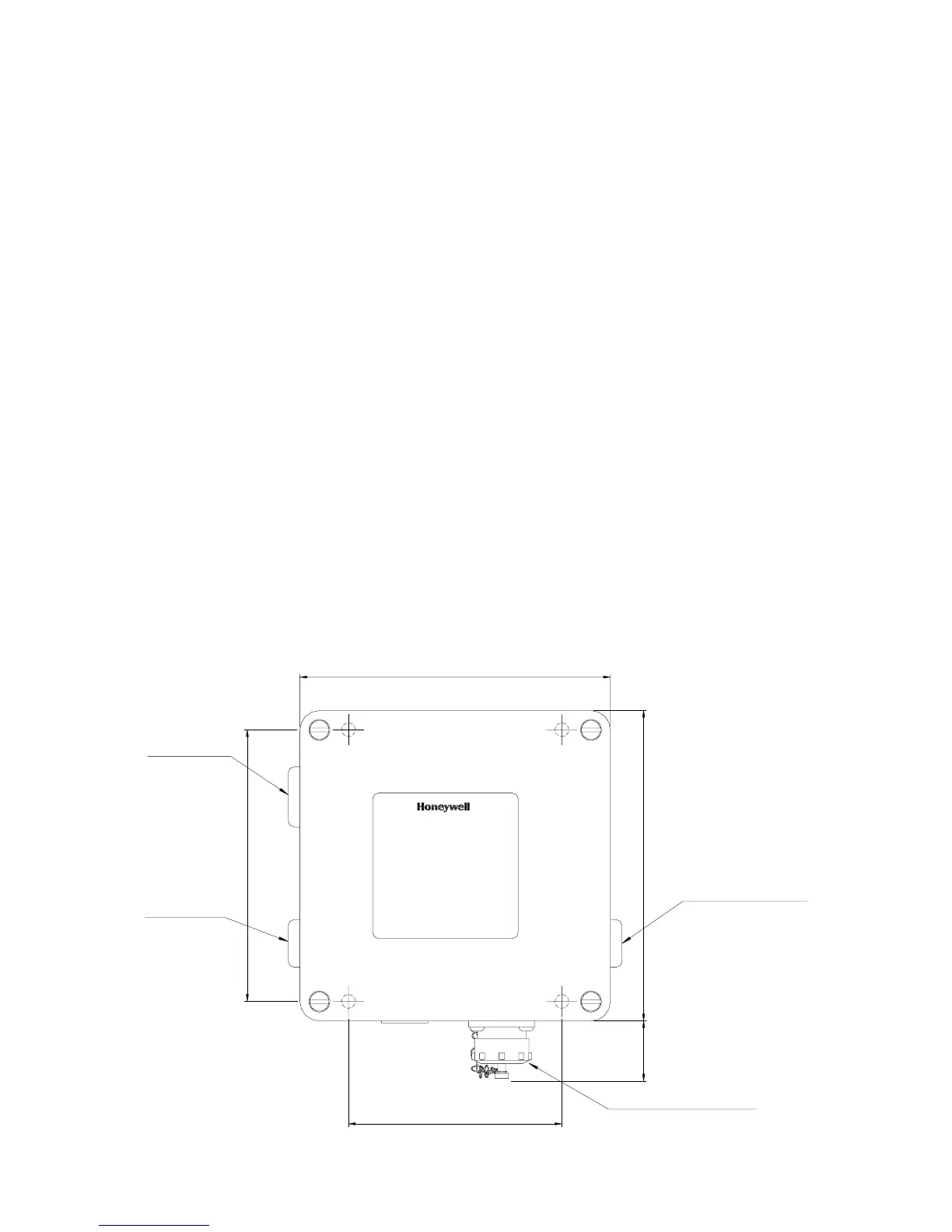
(1) Securely t the Termination Unit at the required monitoring point.
Use the four Termination Unit mounting holes(visible after the lid is removed).
Ensure the communications link entry socket connector is located at the
bottom. This fulfils the requirement to position the Optima sensor horizontally
so that the risk of fouling the gas detector's optical surfaces is reduced.
(2) Remove the Termination Unit lid.
(3) Fit the Optima detector to the left-hand (M25) entry.
(4) Fit ATEX approved cable glands to the Termination Unit cable entries as
required.
(5) Fit the external eld wiring through the cable glands and secure.
(6) Terminate the gas detector and eld wiring.
Refer to Electrical Installation.
5

 Loading...