EXCEL WEB CONTROLLER – INSTALLATION INSTRUCTIONS
EN1B-0256GE51 R0506C
4
Port 2 (Browser Interface)
Port 2 is intended for the connection (as needed, or per-
manently) of a (portable) platform (which must host an
Internet Explorer-compatible internet browser) for the
purpose of operating the Excel Web controller.
This requires the establishment of a remote connection via
RS232 on the PC, plus a null modem cable (RS232 cross-
over cable). Because it offers a much higher speed, we
recommend instead using the USB interface.
Port 3 (Modem Interface)
Port 3 is intended for the permanent connection (if needed)
of a modem (e.g. an analog modem, an ISDN adapter, or
an GSM adapter) for the purpose of communicating with
other front-ends (e.g. 3
rd
-party BACnet front-ends) via
modem.
CF Port LED, Request Button, and Slot
The Excel Web controller features a slot (type-II socket)
into which type-II Compact Flash Cards (CF cards) − but
also type-I CF cards − can be inserted.
Inserting a CF card allows the Excel Web controller's
internal memory (for storing trend records) to be increased.
CF cards having a variety of storage sizes are available
from wholesale and retailer dealers.
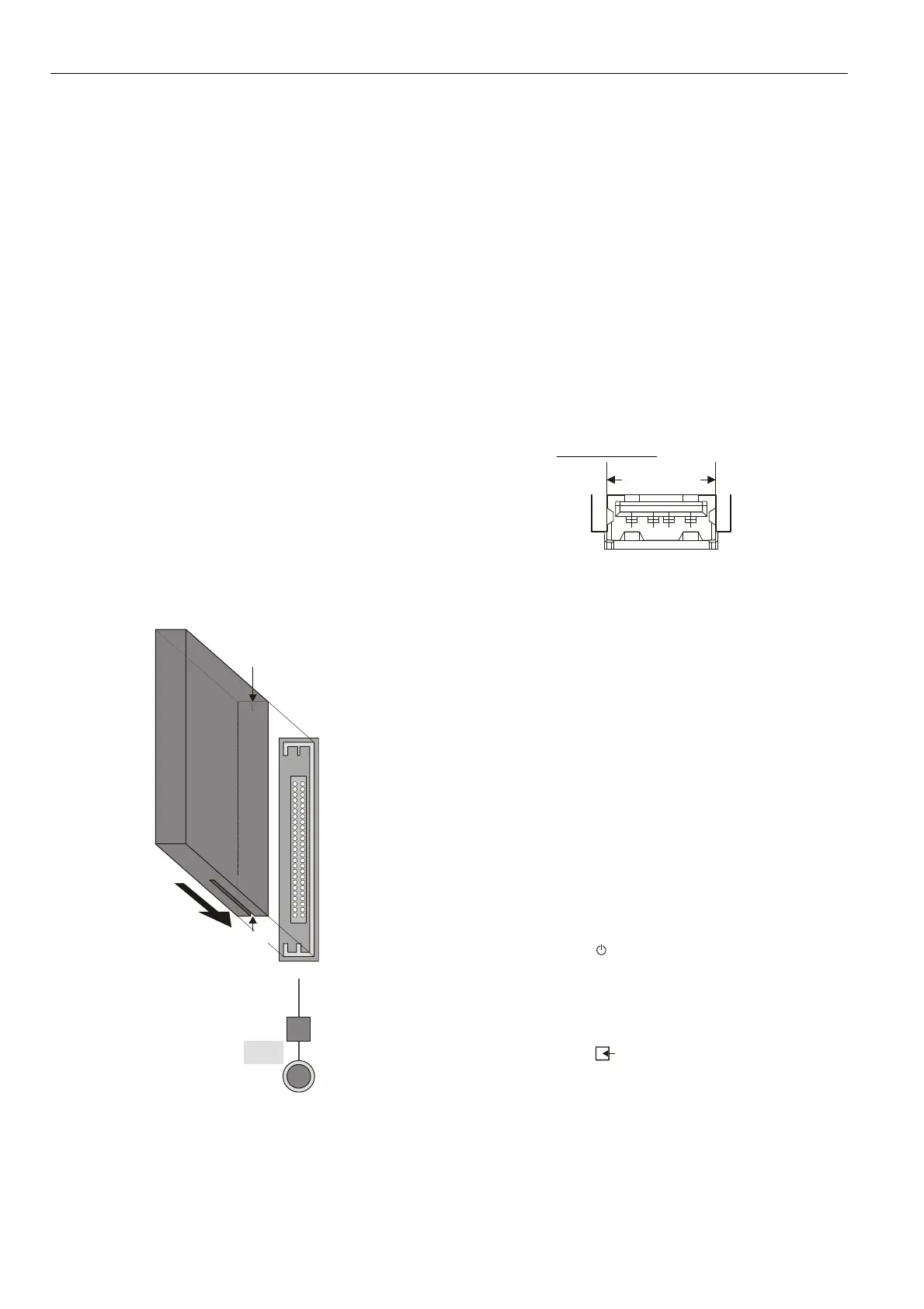
NOTE: Insert the CF card carefully and make sure that it
has the proper orientation (see Fig. 6).
narrow
notch
wide
notch
CF
Fig. 6. Inserting a CF card into the slot
NOTE: Before removing a CF card, always first push the
CF request button and wait (usually just a few
seconds) until the CF LED turns OFF. Violating
this rule could interrupt the transfer of data onto
the card.
NOTE: Upon inserting a CF into a running Excel Web, the
CF will be reformatted, if necessary. Specifically: If
the CF already has the format EXT3, it will not be
formatted; otherwise, it will be formatted, and any
data already present on it will be irretrievably lost.
USB Interface Downloads
The Excel Web controller is equipped with a USB port into
which a standard USB type-A connector can be inserted.
This USB interface is the recommended interface for
downloading applications and firmware via CARE 7.0 and
for operating the Excel Web controller via Internet Browser
in parallel to an Ethernet connection. The following USB
host networking adapter has been approved: BELKIN
DIRECT CONNECT (BELKIN order no.: F5U104 or
F5U104G at www.belkin.com
).
12.5 mm
Fig. 7. USB interface
See section "Option 1: USB (recommended)" on page 9.
LEDs and Buttons
LonWorks Service LED and Service Button
The Excel Web controller is equipped with a LONWORKS
service LED and a L
ONWORKS service button, together
marked "LON" (see also Fig. 1 on page 2). They are used
for commissioning the Excel Web controller and for
troubleshooting.
LonWorks Service Button
When the L
ONWORKS service button is pressed, the service
pin message is broadcast on the L
ONWORKS network, and
all L
ONWORKS tools currently connected to the LONWORKS
network will receive this message.
LonWorks Service LED
The L
ONWORKS service LED can display various behaviors
having different meanings (see Table 2).
Power Supply LED
The LED marked " " indicates whether or not the Excel
Web controller is currently under power. Specifically, when
it is lit, the controller is under power; when it is dark, the
controller is not under power.
Binary Input (terminals 3+4) LED
The LED marked " " indicates the state of the binary in-
put (which is a normally-open contact) located at terminals
3 and 4. Specifically, when it is lit, the binary input is
closed; when it is dark, the binary input is open.
 Loading...


