12 IFP-FFT Manual — P/N 54708:B3 10/28/2021
Installation IFP-FFT Board Layout
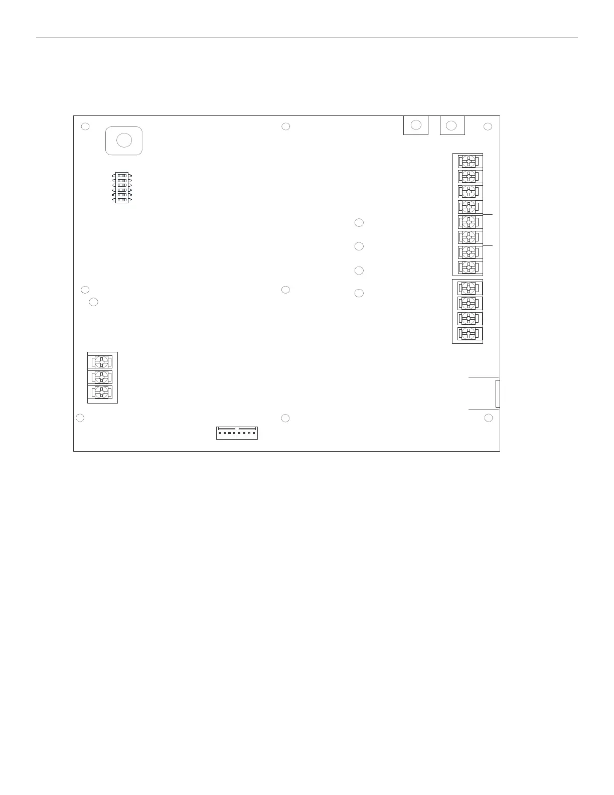
3.3 IFP-FFT Board Layout
Figure 3.3 shows the circuit board that can be installed in the cabinet. If you need to remove the board assembly for repair, remove the seven
mounting nuts which hold the assembly in the cabinet. Then, lift the control board out of the cabinet.
JumpStart
FFT-24 Connector
Status LEDs
local handset
PZT
Phone In
Phone Out
SLC IN
SLC Out
supervised,
power- limited
All circuits inherently power-limited except
the trouble relay.
Not used
DC Power
Non Power
Limited
Trouble
Relay
Accept
DIP
Switches
Power LED
Figure 3.7 Back View of IFP-FFT
 Loading...